2D: Cascade Elevator
Layout Sketches
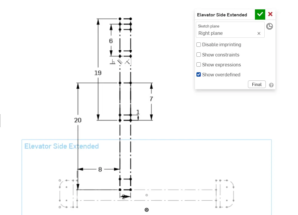
Elevator main layout sketches usually start with an extended side view so you can drive the length of it based off of the extension limits and your required beginning and end position for whatever mechanism you're moving.
Though this elevator doesn't have that context, it's still useful to follow the same workflow of starting with a side sketch, which will contain most important dimensions but can be hard to conceptualize at first.
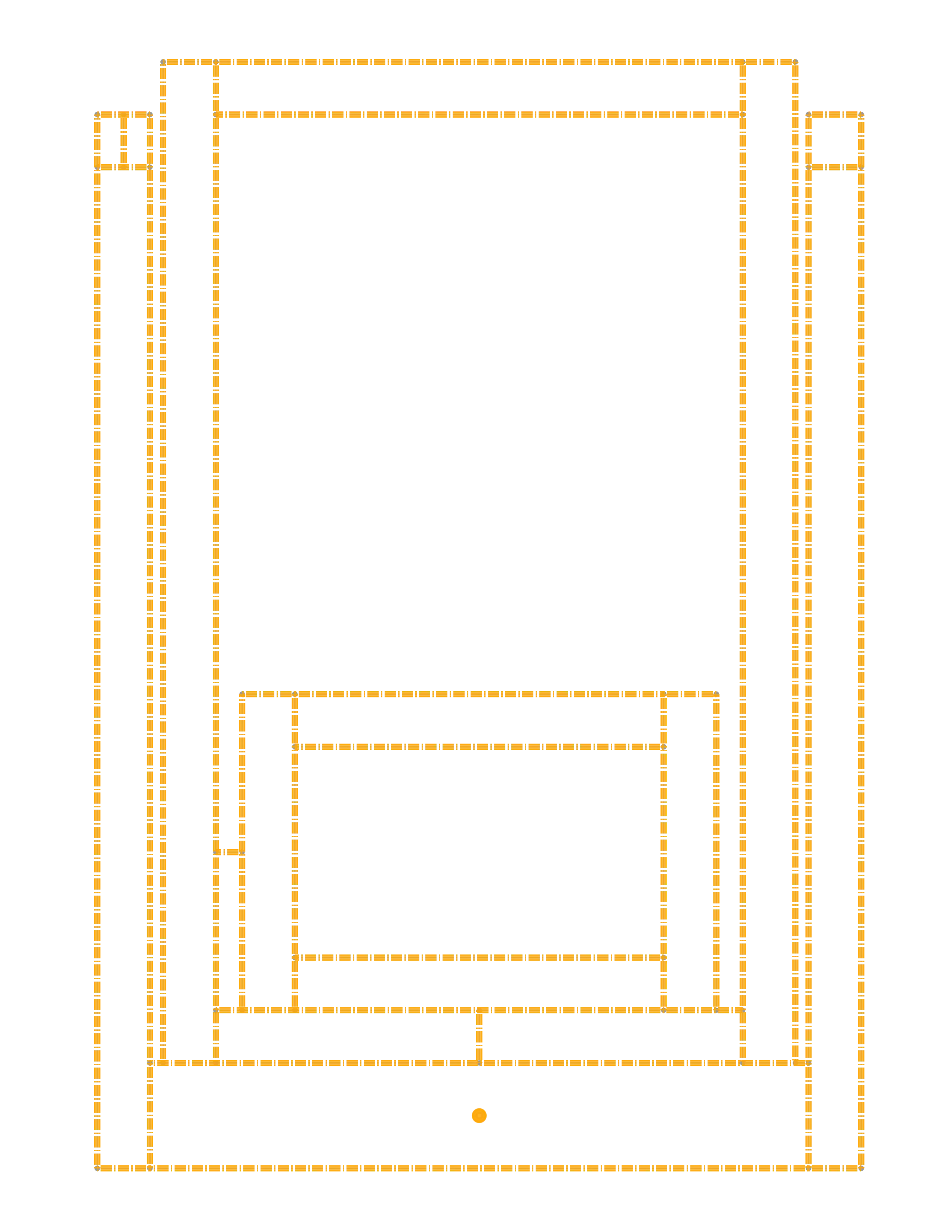
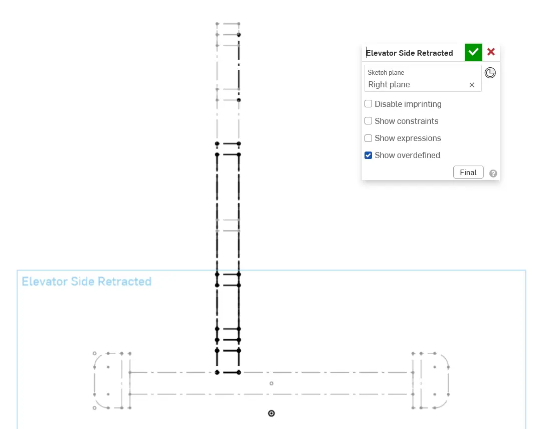
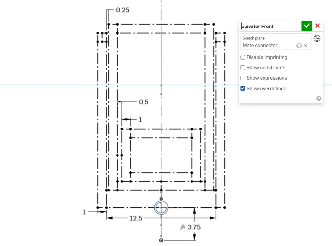
Follow the instructions in the slides to create your elevator layout sketches.
Tip
Instead of creating "extended" and "retracted" views, you can separate the stages into their own individual side sketches to let you "animate" how it moves in the sketch. You can use configurations to do this.


