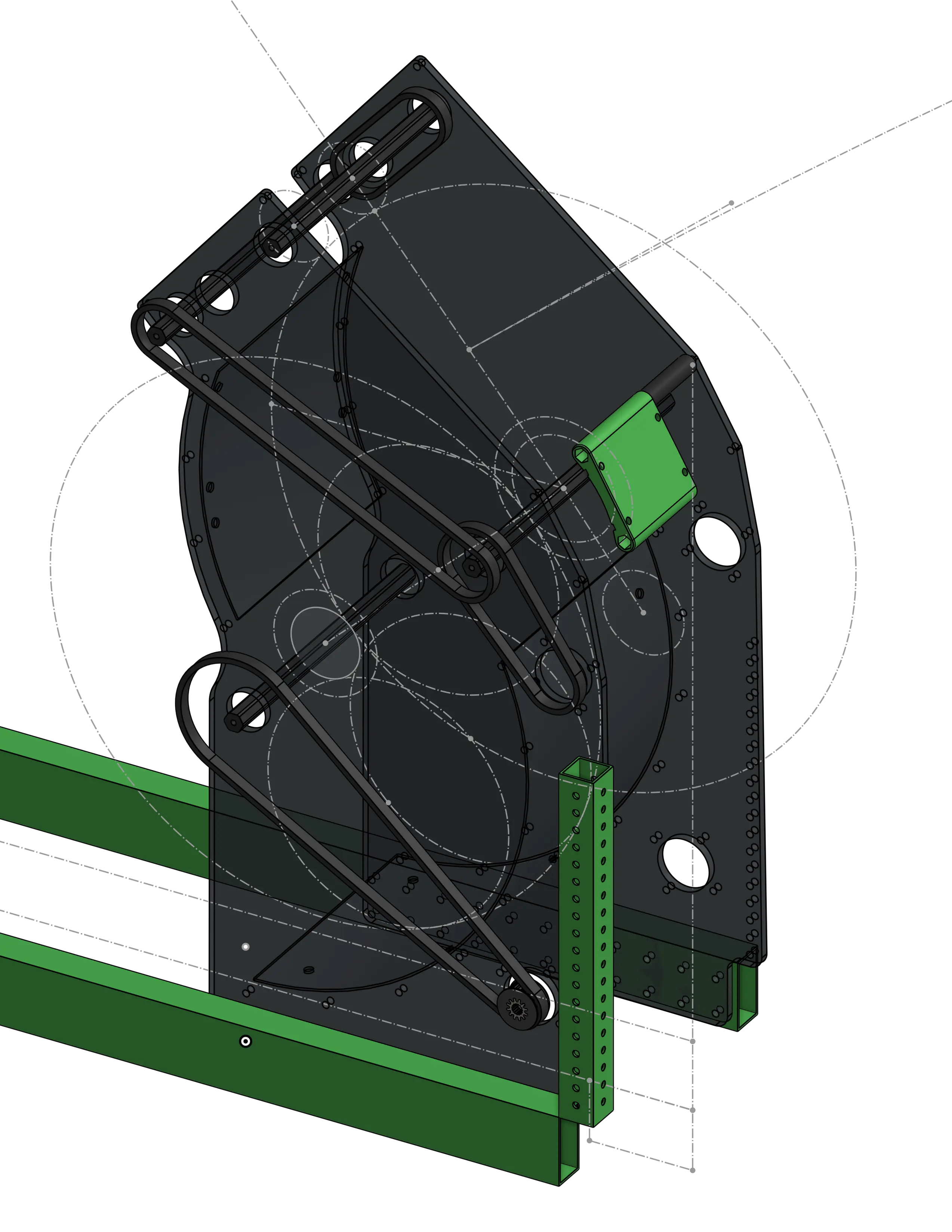
2A: Basic Shooter
Part Studio
Tip
You can use the rollback bar to view the reference shooter part studio at each step of the process.
Structure
- Model your reference drivetrain cross tubes that the shooter plates will mount onto and make them a closed composite part. These will be 8 inches apart to leave room for the ball to travel between the plates.
- Model your main plate on the inside of the cross rails, sketching mounting hardware holes first, including standoffs to hold the bent polycarb following the edge of the large ball path circle concentric to the feeder wheels, then power transmission (motors, belt center-to-center lines, gear pitch circles), then finally the plate outline. Similar to sketching a large gearbox, isn't it? Make sure to extrude it and mirror it for parametric reference for other parts.
- Model the additional 1x1 tube used to mount the front of the shooter to the drivetrain. This helps keep it rigid despite potential flywheel vibrations at high speeds.
Power Transmission
- Model the power transmission components using the
Belt & Chain GenandShaft Generatorfeaturescripts. - Most pulleys will be inserted in the assembly using MKCAD's configurable HTD pulley part (they can all be 3D-printed), but the Kraken x60 pinion pulley for the feeder wheels will use a SplineXS 3D-printed part adapter. Use MKCAD to derive the base pulley into the part studio, and derive the SplineXS 3dp adapter from this document. Perform a boolean subtract operation on the pulley with the adapter to create the cutout, checking keep tools to keep the adapter part. Make sure they're transformed into the correct place on the main plate.
Finishing Steps
- Model the polycarb backing with holes in it to attach it to the standoffs with zip ties.
- Model the 3D-printed camera mount and camera mount spacers for the Limelight 3
