2A: Basic Shooter
Layout Sketch
The following outlines the steps you should take to design your ball shooter. The reference document is provided below:
Initial Layout
- Use the Origin Cube Featurescript to insert the Origin Cube.
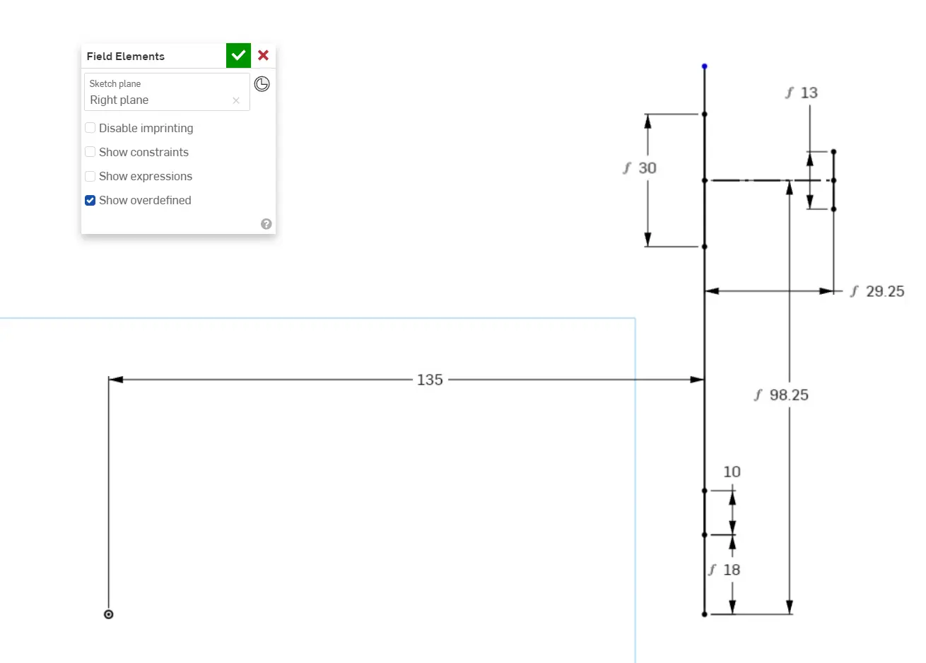
- Sketch any field elements you intend to interact with. There's no hard alignment, but you intend to shoot into the back goal of the "Power Port," so you must sketch that from a side view using the game manual and field layout drawings for reference. Place it 135 inches away from the origin, as that places the center of your robot 15 inches away from the white "initiation line"

- Sketch a side view of your drivetrain + bumpers.
- Sketch a rectangle with your frame perimeter and height limit. This becomes your bounding box on where to design.
Shooter Layout
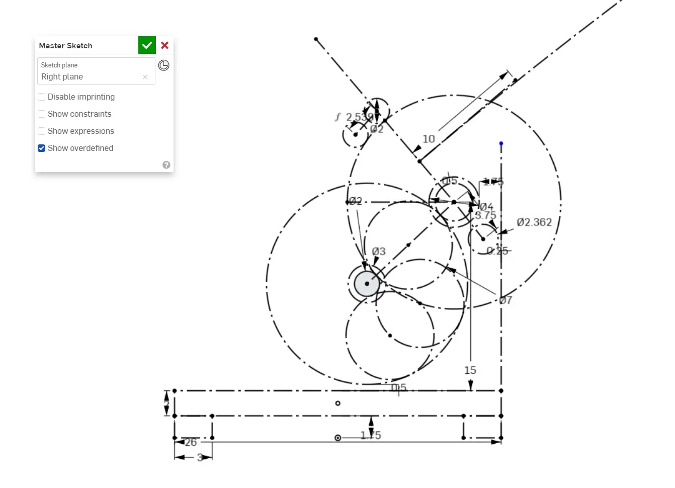
- Sketch your flywheel location, with the flywheels being 4in diameter.
- Sketch another circle concentric with the flywheels, 0.5" smaller in radius. This is to compensate for the compression of the ball.
- Sketch another circle, concentric with the other two circles, and make the outside of that circle 7 inches away from the outside of the 3" compression circle. This large circle is to denote the path of the ball and eventually the bent polycarb the ball slides against.
- Sketch your hood wheels by adding two 2 inch circles tangent to the outside of the large circle. Dimension them from each other using a belt calculator.
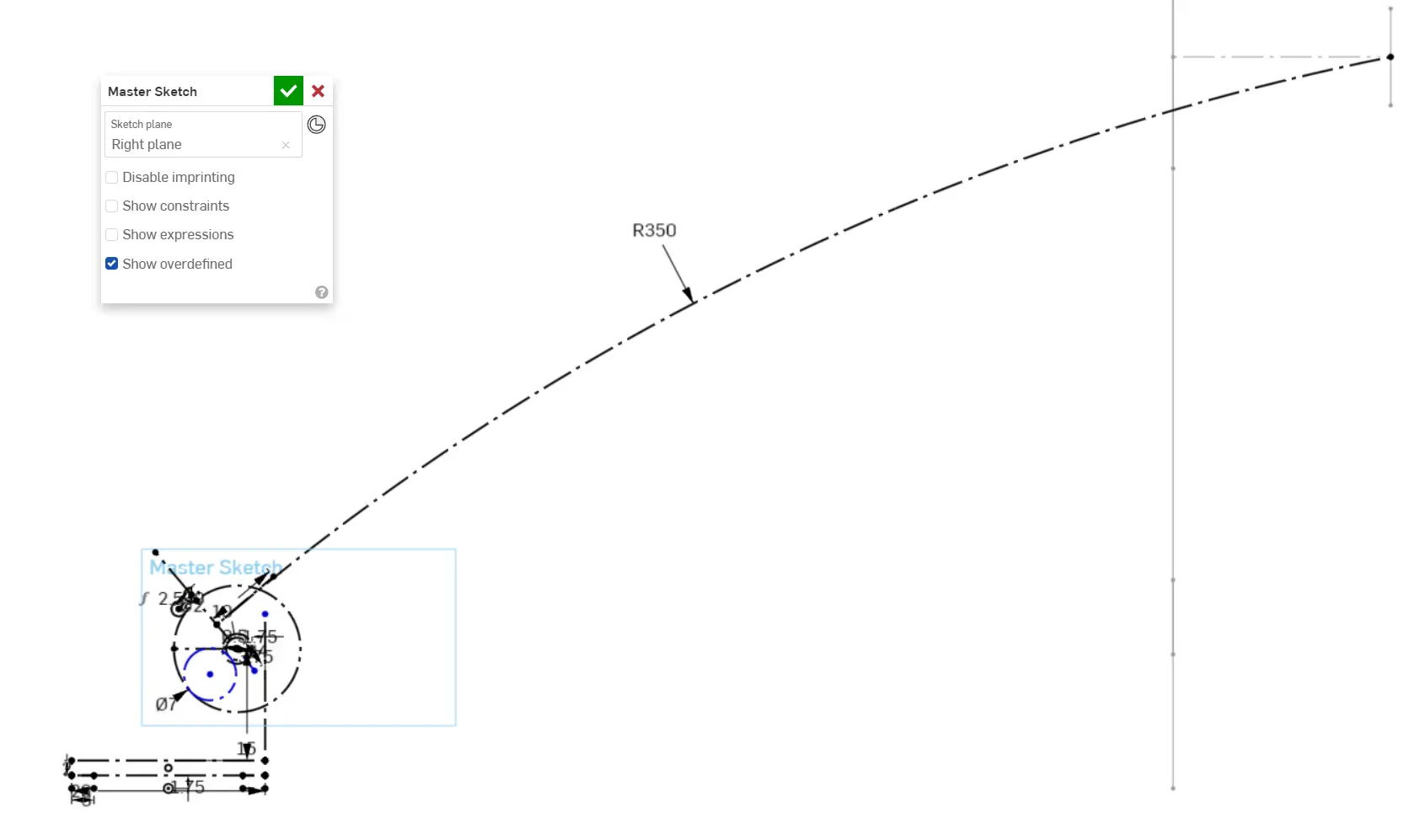
- To constrain your shot angle to the field element placement, since the hood is not adjustable, create a line between the 3" compression circle and the last hood wheel, create an arc from the center of that line to the center of the back goal of the Power Port, and make it normal to the first line you made in this step. Adjust the radius of the arc until you are happy with the arc. The arc itself can be adjustable in real life depending on how far away from the goal you are by adjusting the speed of the flywheels.

- Decide where you want the motors for the flywheels to go and dimension them away from the flywheel center using a belt calculator.
Feeder
- Now decide how the shooter is being fed. This depends on the amount of space in the rest of the indexing system, but here we're using an S-shape feeder because the balls are being fed from the front and shot from the back. Sketch two concentric circles for the feeder wheels (green compliant wheels), 3" and 2" to account for the compression of the wheels, making the 2" circle concentric to the large ball path circle. Add a final large ball path circle concentric with your feeder wheels and make it tangent to the original 3" compression circle of the flywheels.
- Sketch 7" circles representing the power cells to further demonstrate the ball path.
Now make sure all the geometry in the main layout sketch is fully constrained (black). Constrain any unconstrained geometry arbitrarily if you need to.
