1A: Onshape Fundamentals - Section 2
Introduction
At this point you should be an expert at making tubing frames of various shapes and sizes. These frames will not stay together without something to attach to. That's where plates come in. This section will be primarily focused around how to model plates for various purposes.
What Are Plates?
In FRC, plates are used everywhere and are made out of a couple different materials.
Plates have two main functions in FRC: they allow you to connect structural pieces together and mount transmission components like motors, axles, or mechanisms to the frame. A plate used solely to connect two pieces together is also sometimes referred to as a gusset or bracket.
Below are two examples of plates being used in FRC.
Plate Examples
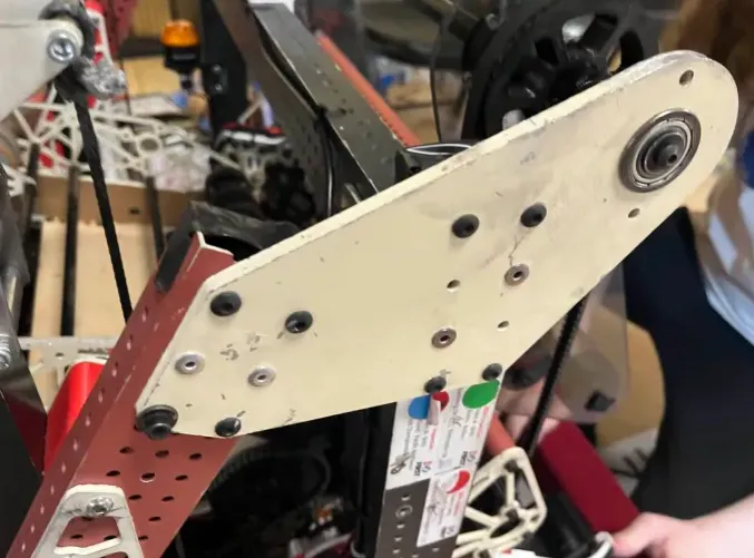
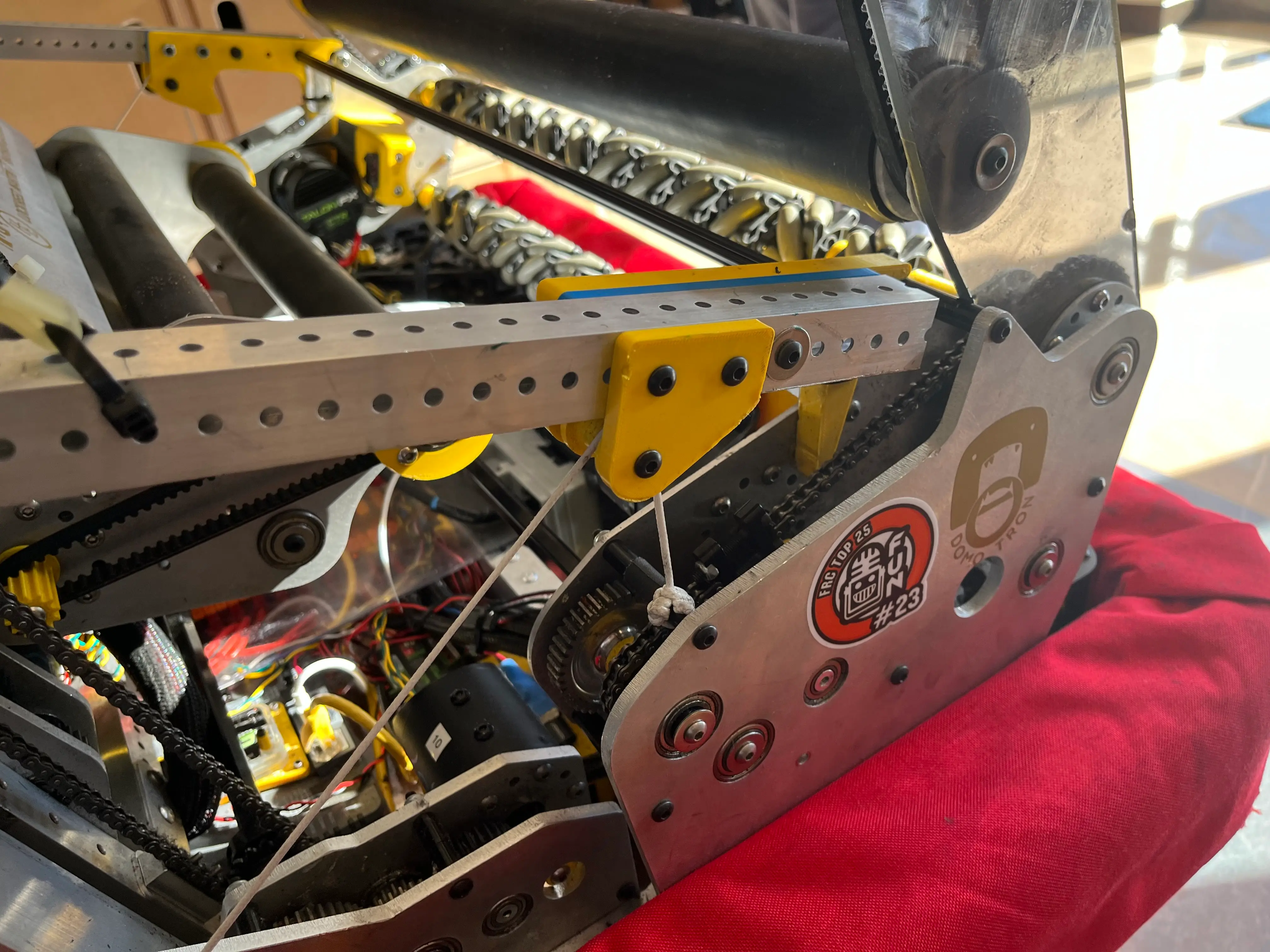
Background
Since your tubes are always in 0.5-inch increments, your plates allow you to bridge the gap between uneven distances. This is possible because plates are CNC manufactured allowing for completely arbitrary hole spacings.
It's this arbitrary hole spacing that is key to think about when designing plates. The purpose of a plate is to place mounting holes where you want them; the material that makes up the plate only exists to position mounting holes and create lines of support, like when using a triangle gusset.
A plate sketch is composed of circles for the holes, arcs for larger corner fillets, and lines to complete the shape. When making the shape of a plate think about the shape that would be made by tying a string around all of the mounting holes on a given plate. Here is a video demonstrating this concept for a very basic plate. No need to follow along here, just watch.
This video also shows off the tangent constraint! This is one of the most frequently used constraints when designing plates since each mounting hole will have an arc around it to form the perimeter of the plate. The tangent constraint allows us to create a tangent line for an arc or circle. This is important to “smooth” out our plate. We don’t want sharp edges!
Exercise 1: Plate Workflow
Your task is to make a very simple plate with two bearing holes. Bearings come up everywhere in FRC to help reduce friction on moving components. This is the same type of plate as shown in the prior video.
To get started, find the "Exercise 1: Plates" part studio in the "Section 2" folder in your copy of the template document and follow the plate workflow below to practice making a couple plate shapes.
Plate Workflow
- Draw an arc around each bearing hole, dimension one of the arcs to be 0.25" away from the hole
- Set the two arcs to be equal in radius by using the equal constraint.
- Draw lines connecting the arcs
- Set the lines tangent to the arcs to align everything.
Tip
Constraints can form accidentally when sketching. Part of an arc might accidentally get horizontally or vertically constrained.
You can delete constraints by hovering over a sketch entity (line, arc, circle, etc.), clicking the icon of the constraint you want to delete (the involved entities will be highlighted), and clicking the delete key on your keyboard.
Holding shift when creating geometry also turns off auto constraining. If you get stuck you can refer back to the video for guidance.
Complete?
After finishing, delete your plate outline, and repeat these steps 2-3 times or until the process feels natural and you do not need to reference the steps. You can close the workflow dropdown if it helps you stop looking at it.
Try adding a third bearing hole into the plate! You will end up making dozens of plates over even just a single FRC season, so getting comfortable with these steps is a must.
Once you've gotten comfortable with the workflow, feel free to move on to the next exercise.