1A: Onshape Fundamentals - Section 1
Exercise 5: Building a Box Superstructure
Introduction
Frames made out of box tube can added to the top of a drivetrain for extra mounting for more parts of subsystems, like a shooter or an arm.
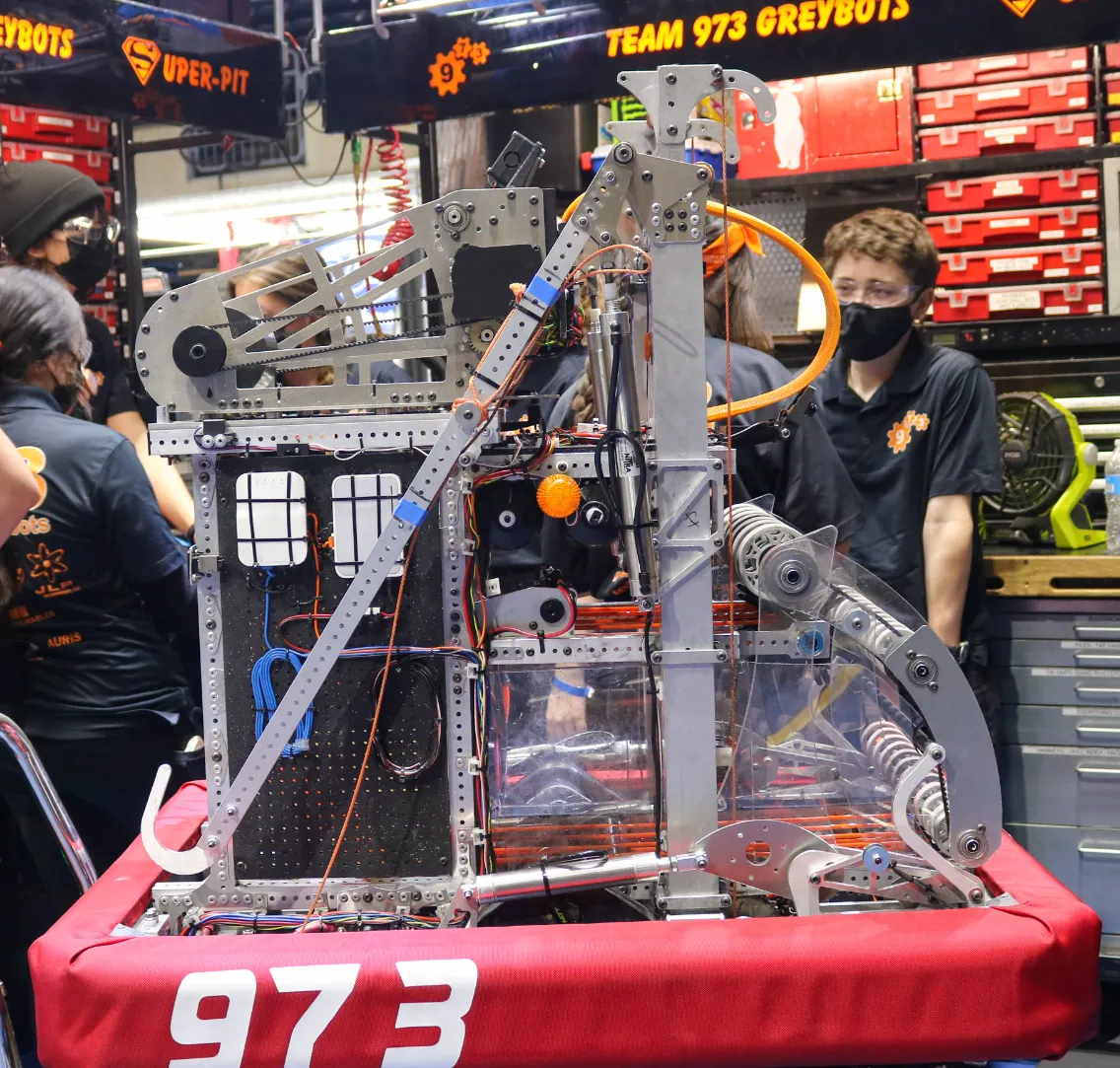
In this exercise we'll be adding a simple box tube frame to the drivetrain you made previously.
Layout Sketch and Drivetrain
- To properly plan this out, we must create a side layout sketch (the used previously in Exercise 5).
- Start by inserting the origin cube feature script that you added in required course tools. Remember you can look things up using
Alt + C! -
Make a new sketch, select the
right plane, and start copying this sketch. Figure out the constraints you need yourself to replicate it perfectly.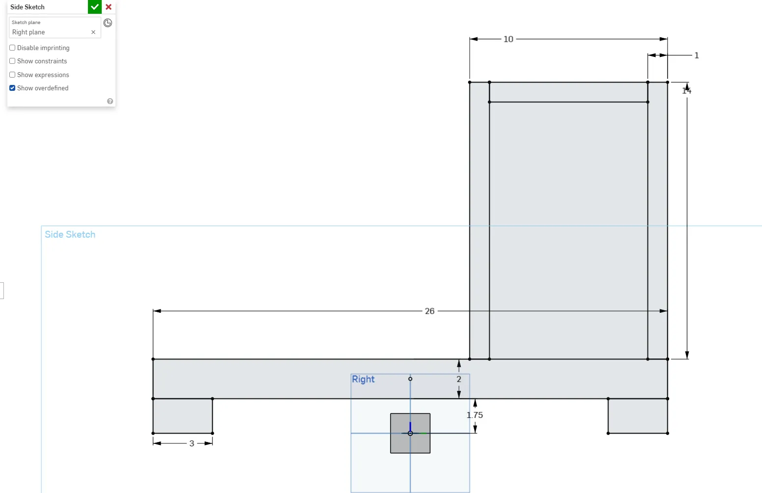
Box superstructure sketch Origin Placement
The wheels are the 1.75-inch blocks on the corners of the tube. If that's the case, where is the origin placed in the side layout sketch? Why do you think it's placed there? Imagine if you looked at the robot in real life to the side.
-
After the side layout sketch is done, create the swerve drivetrain frame in your part studio according to what you remember from the last exercise. (Remember to select the mate connector!)
Tip
If you struggle, refer to the previous video after trying
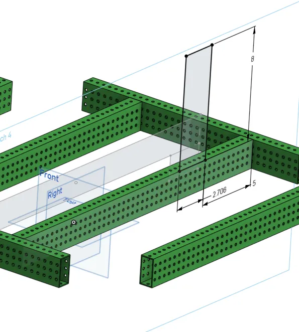
Design Intent
Let’s make this drivetrain a square. How would you approach your top sketch to avoid using any unnecessary dimensions? You should only need to define your swerve gap, the distance between your cross tubes (8 inches), and your tube offset.
Hint
What length is already defined/constrained? Can you use the equal constraint?
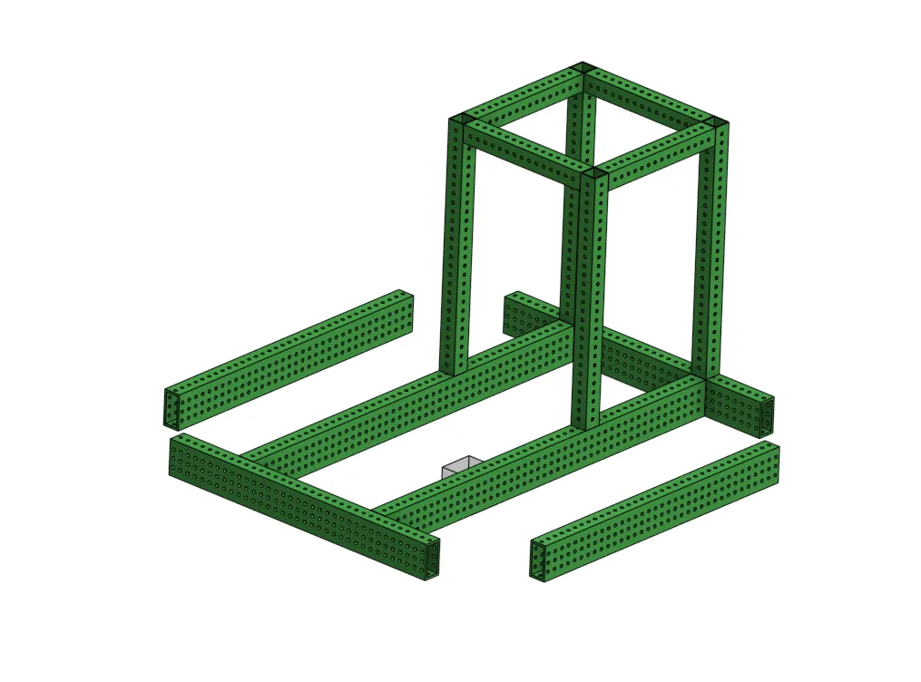
Modeling the Frame
So far, sketches have been created on default planes and mate connectors. In order to model the box tube for the frame on top of the cross tubes, the sketch to create the tubes should be created on the face of the cross tube, because that's where you want that tube to be, even if the cross tube changes position.
Design Intent
This is called modeling with "design intent." There are many different ways to model something, but you can choose specific ways based on what your intent for a part or the overall design is. This can also help you avoid creative blocks and keep your CAD from creating errors when the design changes.
Watch a demonstration of this sketching technique below.
Now that you’ve seen a demonstration, try to complete the box tube structure by creating a sketch on the face of the cross tube and projecting lines from the layout sketch into the new sketch with the use tool.
Requirements
- The box frame should be made using 0 new dimensions total, both in the sketch and the extrude
- Edit tube converter to use 1/16" thick walls and change “centered on tube” to “auto offset”
Tube Offsets
The distance between the edge of your tube and your hole differs for drivetrains and typical use. If you use "centered on tube" for your regular box tubes your hole spacing wont be correct. Only use “Centered on tube” for your drivetrain rails!
Finishing Up
Once you finish, take a 5-minute break.
After you come back, try to improve or correct any mistakes you find. Once you finish, compare your workflow with the solution. What thought process led you to do something different?
Follow the short video below to learn how to rename your features, then rename the sketches and features in your part studio. Moving forward, we want to always name our sketches and features.
After you're done renaming your features, move on to the next exercise.