1A: Onshape Fundamentals
Exercise #2: Box Tube and Gusset Joint
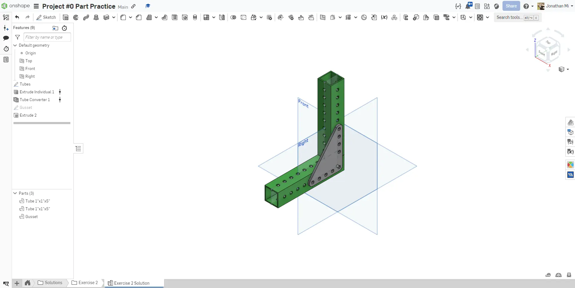
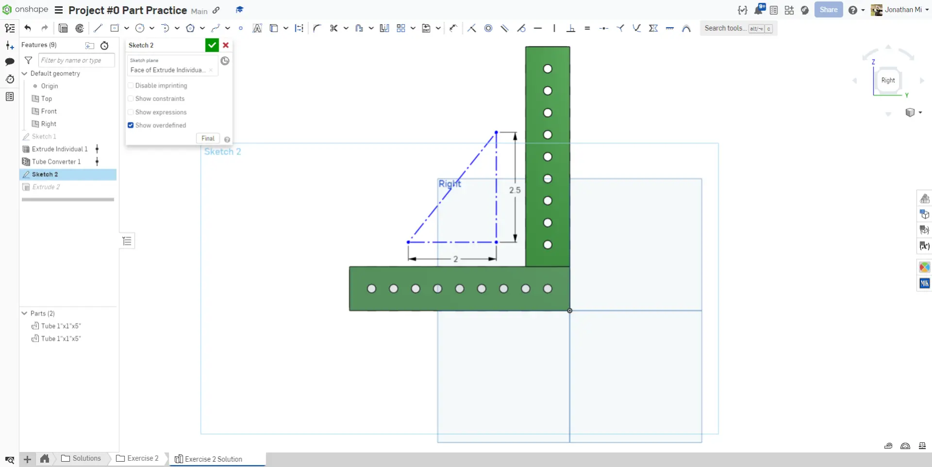
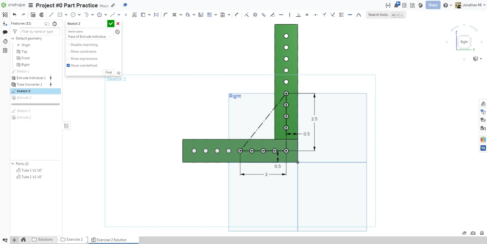
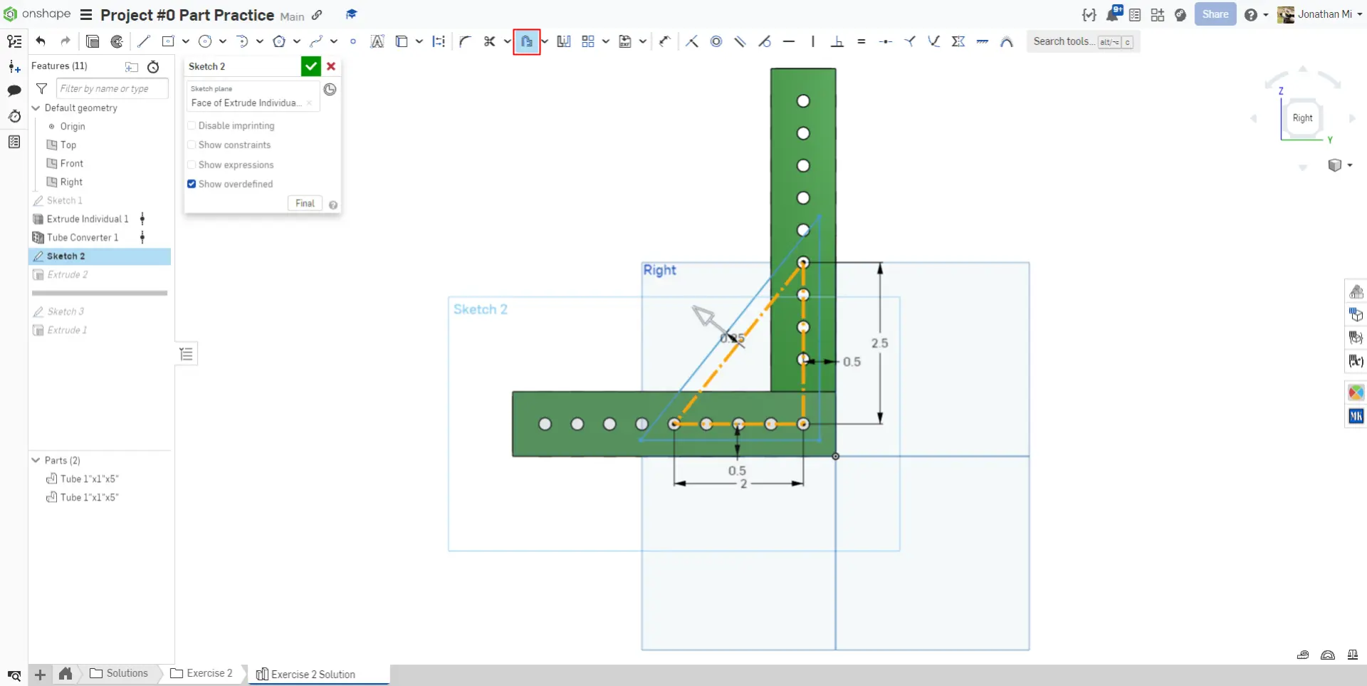
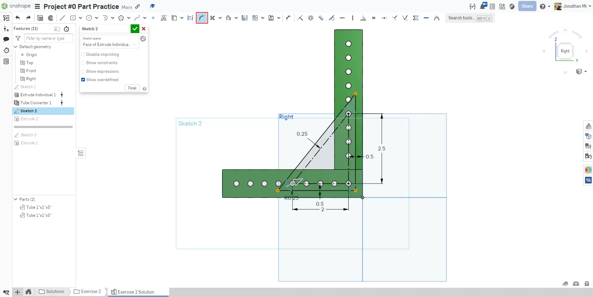
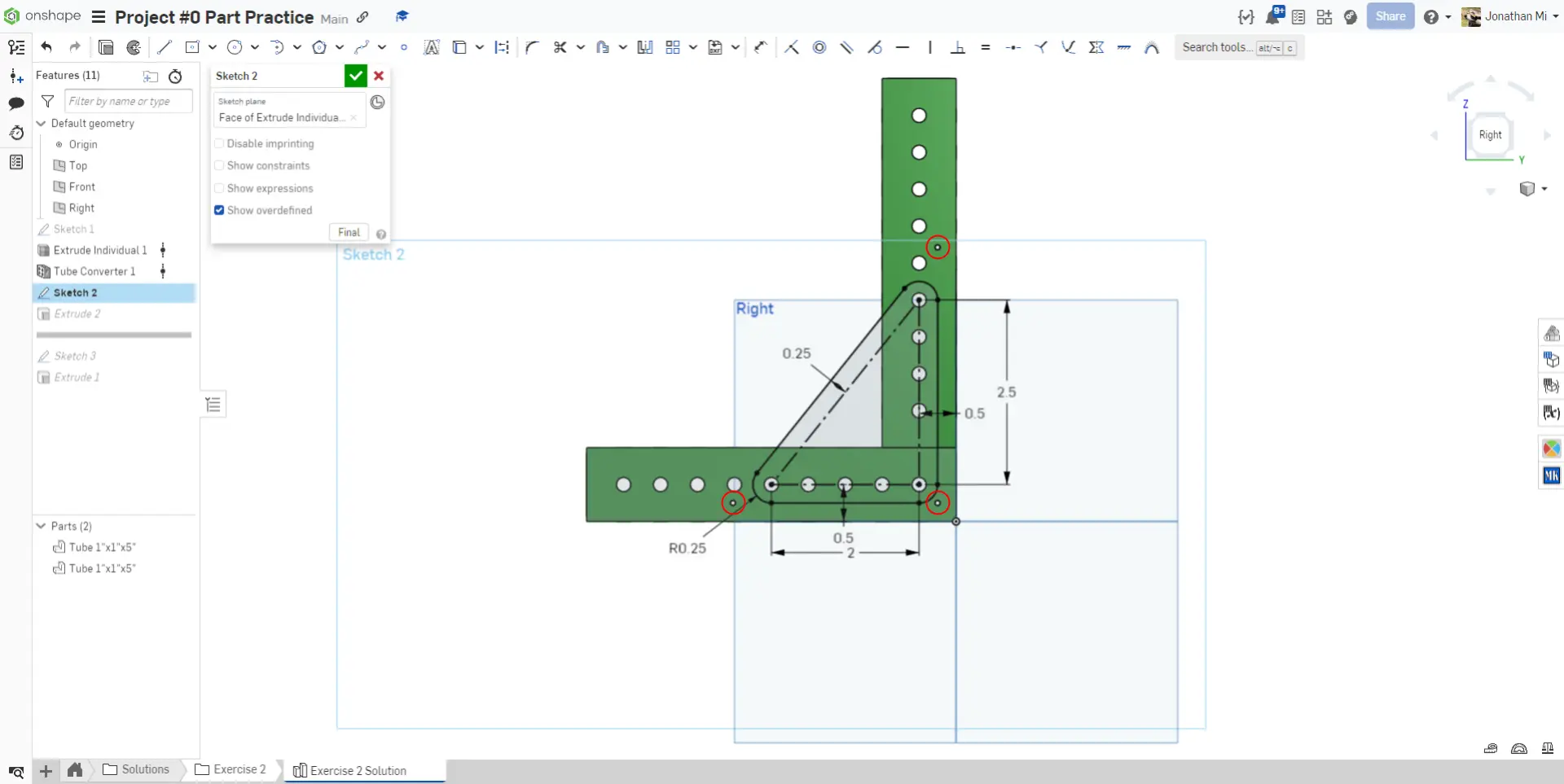
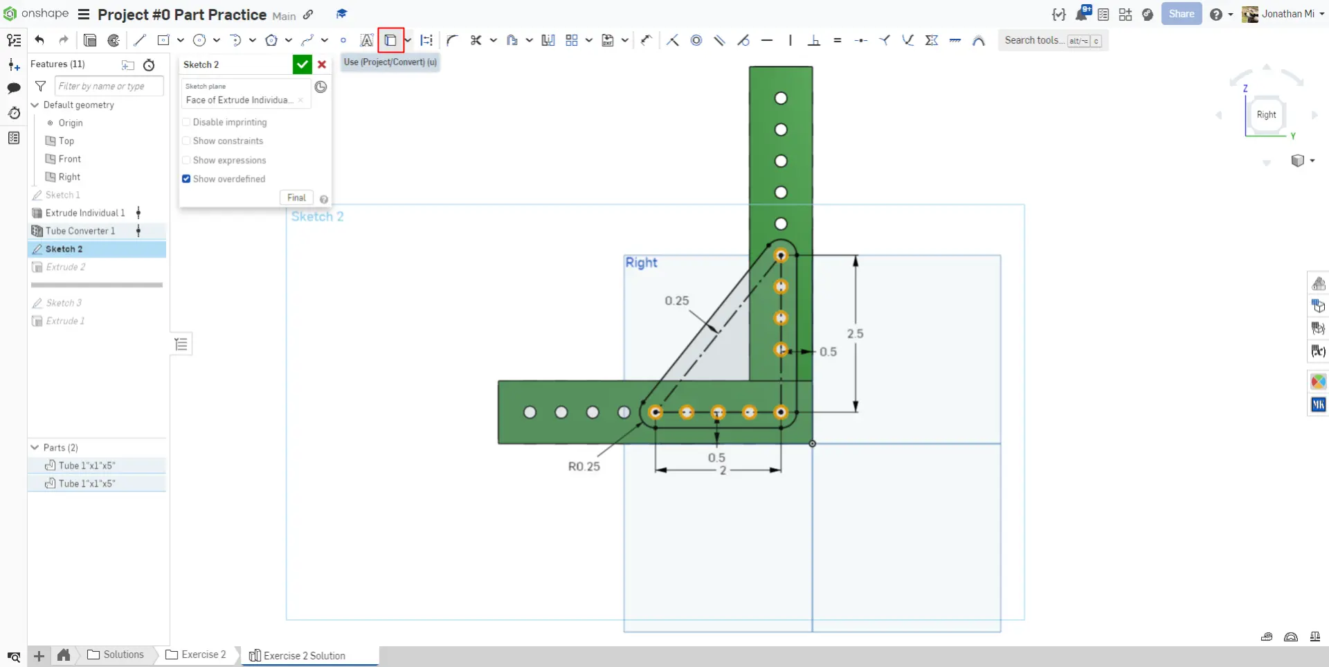
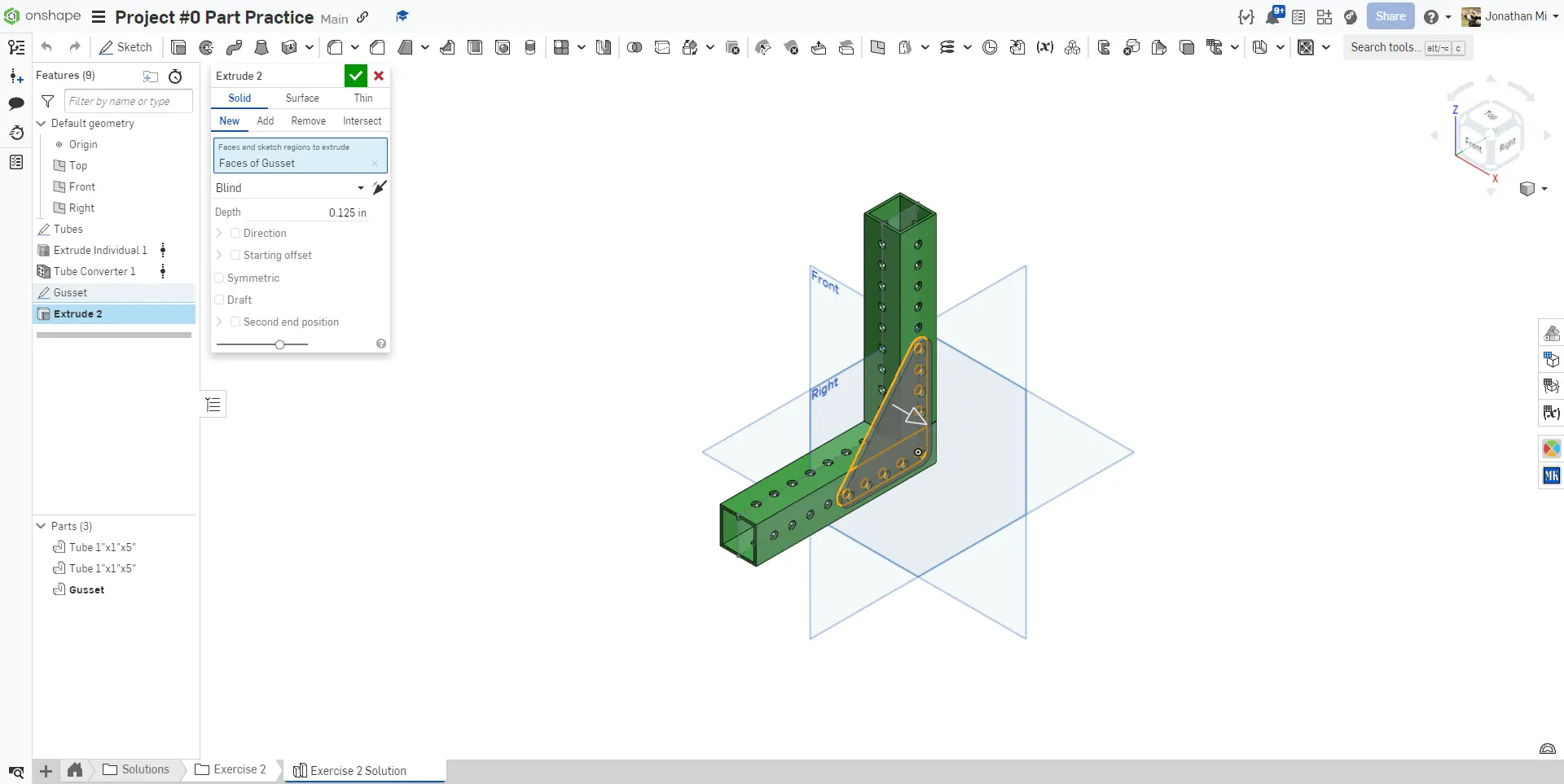
For this exercise, you will design two box tubes attached together with a gusset. This gusset will be created in the same part studio as the tubes that it is connecting!
Gussets
Aluminum box tubes are commonly connected together with 'gussets'. A gusset is a flat plate that, when attached to both tubes, helps create rigidity in the structure.
Gusset Example

Featurescripts
Warning
If you haven't already, please add MKCAD and the required featurescripts for the learning course.
You will utilize the Extrude Individual and Tube Converter Featurescripts for this exercise. Do not use the Gusset Featurescript for this exercise.
-
The
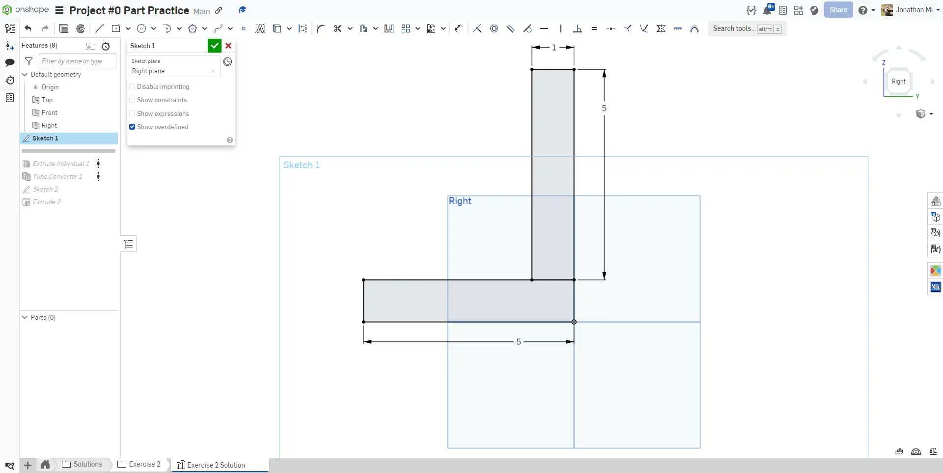
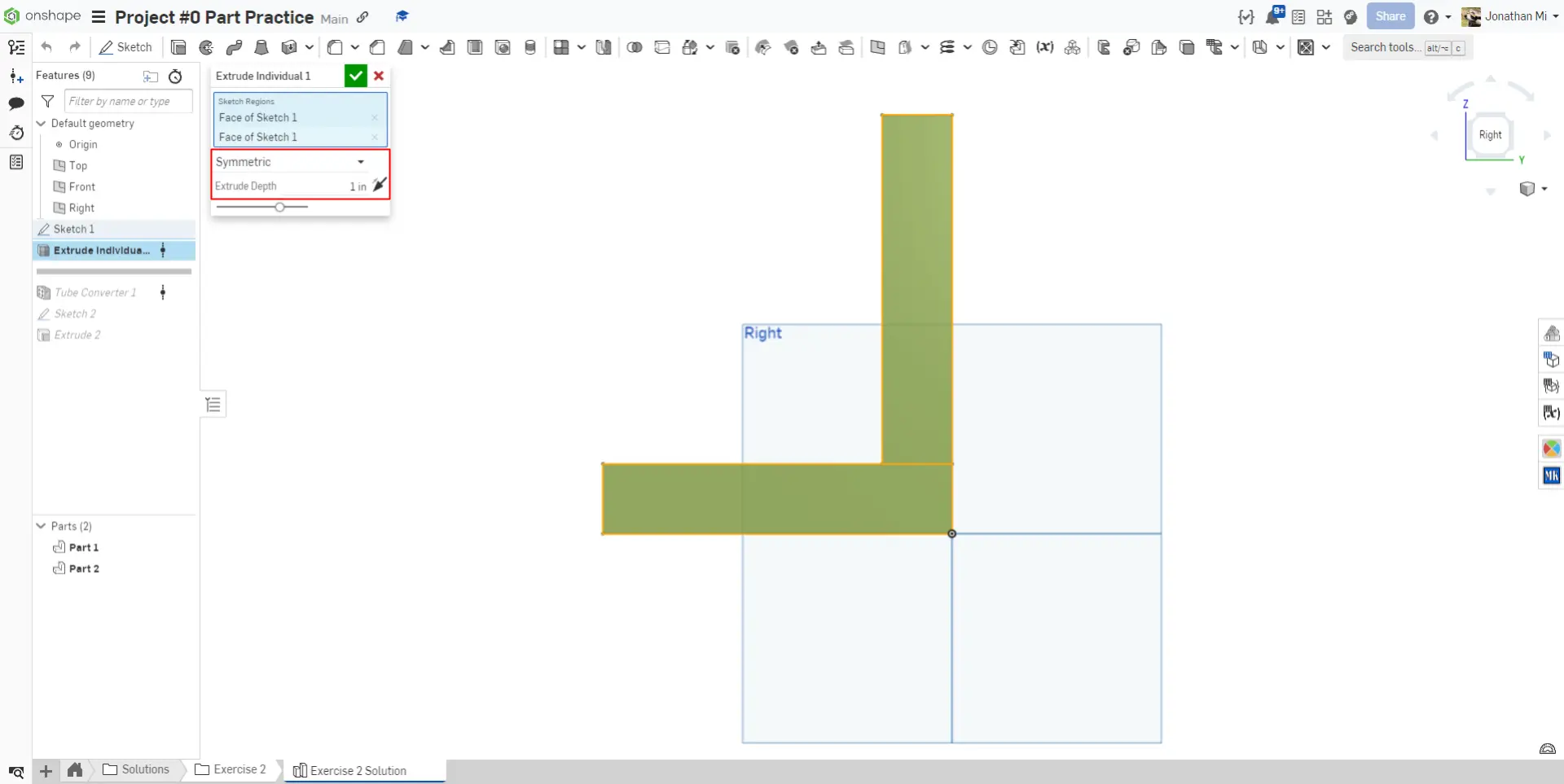
Extrude individualFeaturescript enables you to extrude sketch regions without merging them. In this exercise, if you were to extrude the sketch of the tubes with the standardExtrudetool, only a single part would generate. -
The
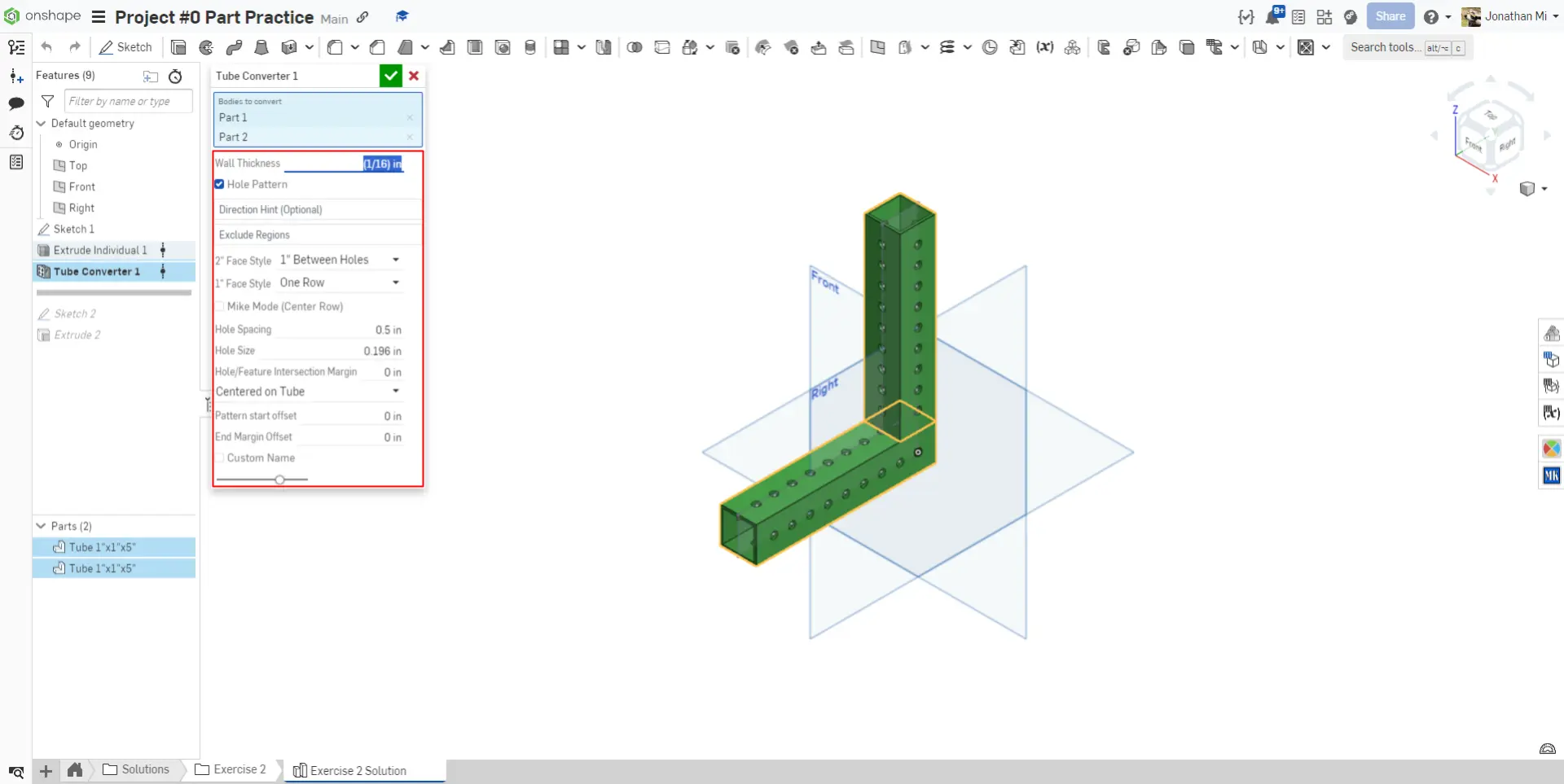
Tube ConverterFeaturescript condenses the steps of shelling, sketching and dimensioning holes, and extruding holes into a single, customizable feature to easily model tubes.
Instructions
Creating New Parts
When extruding a sketch in a part studio, you can decide whether to Add to existing geometry, or to create New geometry. New creates a new body, whereas Add will merge the feature with existing parts. Make sure that when you extrude your gusset, you tell Onshape to create a new part.
Navigate to the "Exercise #2 Gusset" tab in your copied document and follow the instructions in the slides to complete the exercise.
Verification
Make sure to have you and/or a more experienced member/mentor of your team review your CAD! Your parts should weigh a combined 0.27 lbs.
In this exercise, you can begin to see the power of Featurescripts. What would have been a number of sketches, extrudes, and shells to create the tubes is packaged into a single, easy to use custom feature.

