1A: Onshape Fundamentals
Exercise #1: Simple Box Tube
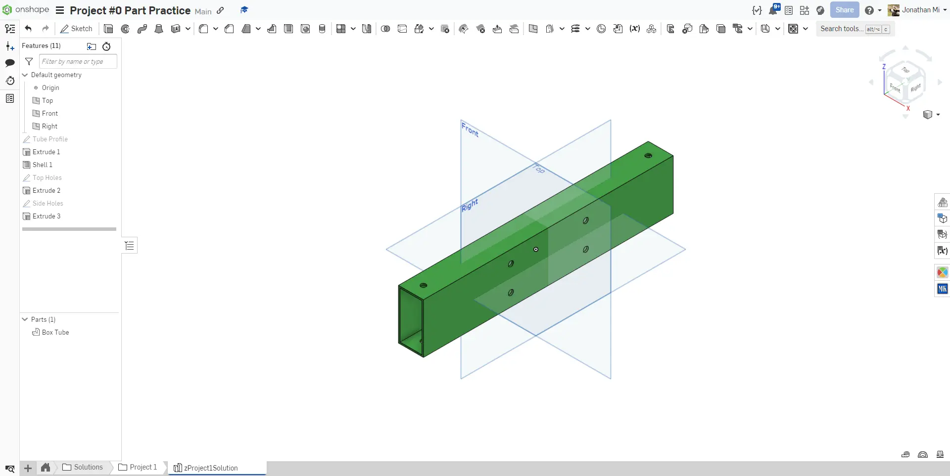
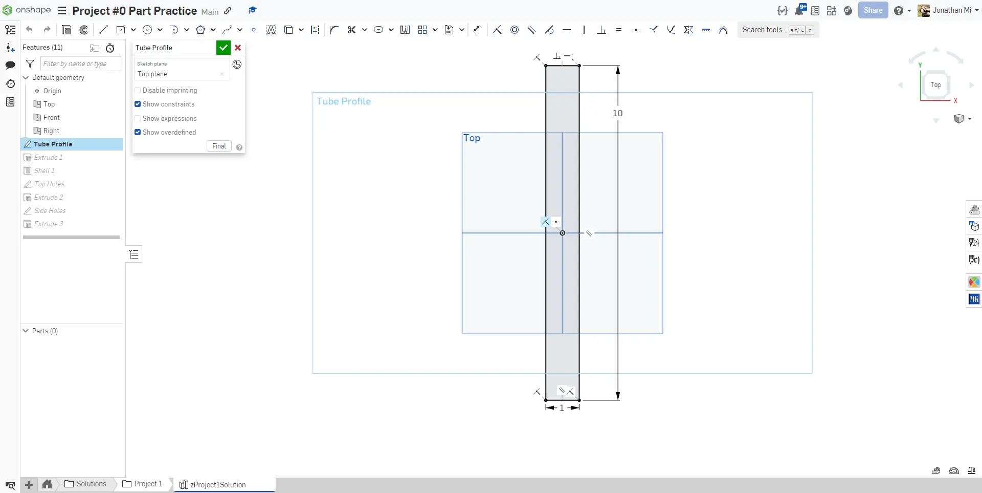
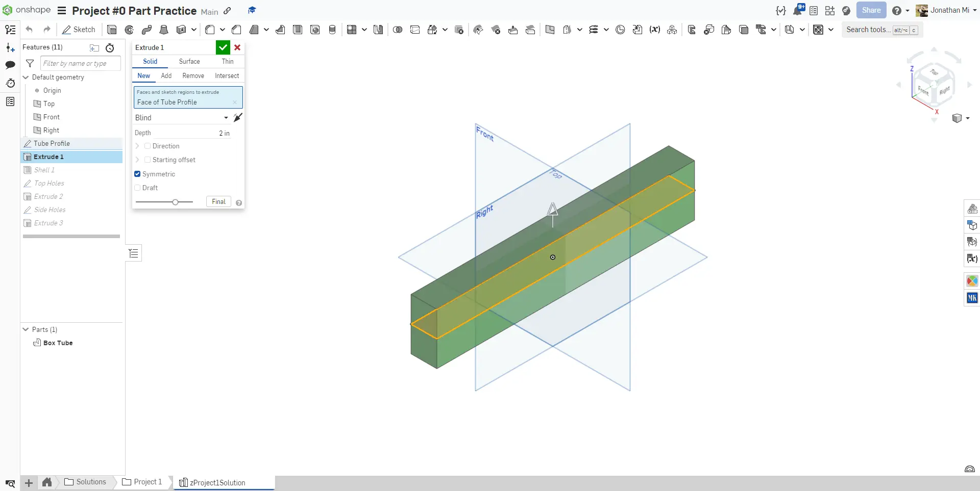
For this exercise, you will be modeling a simple 2x1 with some holes in it. For this exercise, do not use any Featurescripts.
Box Tubes
In FRC, robot structures are typically constructed out of aluminum box tubing, similar to wood beams for a house. Aluminum box tubing is commonly found in 2"x1", 1"x1", and 2"x2" sizes with 1/8" (thickwall) or 1/16" (thinwall) wall thicknesses. Box tubing is typically referred to by its size, eg: 2x1, 1x1, and 2x2 (Spoken as "two-by-one", "one-by-one", and "two-by-two"). For the rest of the learning course, we will use this notation when referring to box tube.
Instructions
Navigate to the "Exercise #1 Box Tube" tab in your copied document and follow the instructions in the slides to complete your first exercise.
Note
Some sketches and features have been renamed (i.e. "Tube Profile"). You can rename sketches and features by hovering over the name in the dialogue box and clicking the pencil icon, or right clicking a sketch or feature in the feature list and clicking "rename".
Verification
Make sure to have you and/or a more experienced member/mentor of your team review your CAD following the instructions on the previous page! Your box tube should weigh about 0.35 lbs.
Construction Geometry
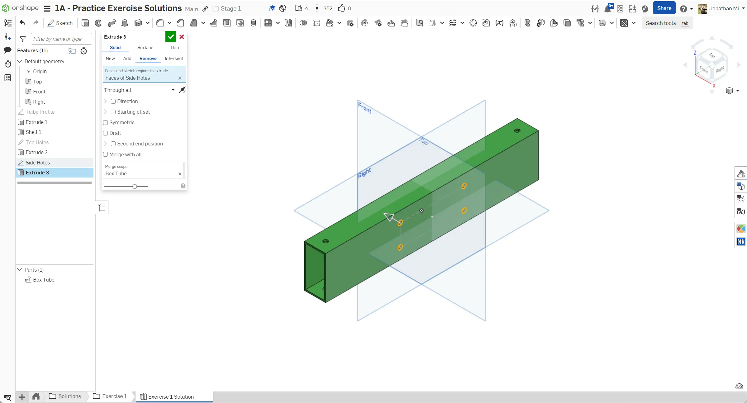
Notice how we utilized construction geometry to define the location of the holes on the 2" face of the tube. Using construction geometry to assist with sketching makes your parts more parametric and betters conveys design intent compared to manually specifying the location of each hole with dimensions.


