0C: Navigating Onshape
Navigating Documents
An Onshape document is not a CAD file, but a container that holds data related to a project, including any number of part studios, assemblies, drawings, and other media/files. It can be versioned and linked to from other documents. There are two main types of environments in a document: part studios and assemblies.
A document has some defined regions that stay generally consistent in both main environments.
- Document Toolbar: You can manage the document, navigate back to documents page (click logo), and view versions and history.
- Toolbar: Changes depending on the environment, but contains all the features you use to perform actions in Onshape. Most of these have keyboard shortcuts (full list in the help menu).
- Tab bar: Organizes different tabs in the document. Can be sorted into folders. Add new folders and tabs to the document by clicking the plus on the bottom left.
- Left Side (Feature/Part/Instance/Mate List): Breaks down how parts/assembly was made.

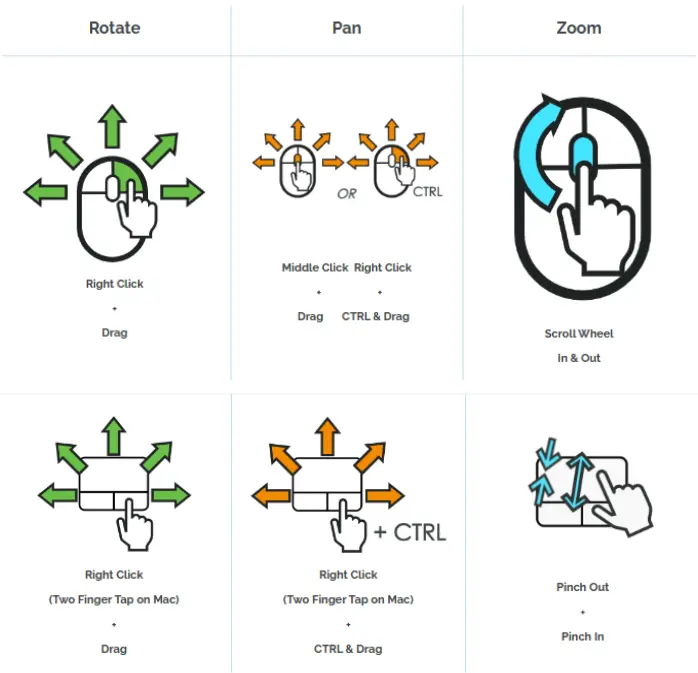
The space in the middle is called the graphics area. You can interact with the model by selecting entities or rotating the view.
Selection
Onshape has persistent selection, which means each left click on a face or entity adds it to a selection group. Clicking an entity again will deselect it, while clicking in the blank space or pressing the spacebar will deselect all entities.
Measurement
To measure lines or distances, select the entities you want to take the measurement of and the numbers will display next to the tape measure in the bottom right of the graphics area. Click the tape measure for more detailed measurements.
One of the main differences between Onshape and other CAD systems is the part studio.
A part studio is an environment where you can design and model one or more parts at a time and add robust relationships between them. You do this using a series of sketches and features. This helps build design intent between multiple parts easily without having to switch between different files.
Part studios provide many different tools for designing, creating, and manipulating parts, most of which you'll learn through Stage 1.
- Dialogue Boxes: Each feature and sketch pops up a dialogue box with options to configure and confirm it
- Toolbars: The main toolbar contains all the tools you'll need to create parts, most of them with a keyboard shortcut for quick usage.
- When editing sketches, the feature tools are replaced with sketch tools to assist in creating 2D geometry.
- Both toolbars have basic geometry creation and geometry alteration tools.
Note
The part studio is for designing the parts, while an assembly is used for putting the parts together and defining motion (this means only model one of each part if there are duplicates and duplicate them in the assembly instead.)
Assemblies are for positioning and establishing movement between parts. The main function for this "mates", which establish the degrees of freedom between parts. Parts can move freely in an assembly before their position/movement is defined with mates. The purpose of assemblies in Onshape is the same as in other CAD programs, but the workflow is significantly different.
Info
The assembly workflow will be taught through the learning center and exercises throughout stages 1 and 2.
Using the assembly toolbar, you can:
- Insert parts and subassemblies
- Different kinds of mates (restrict different degrees of freedom)
- Special tools for movement and replication
When using a mate:
- Every part and face generates mate connectors at smart spots
- You can manually create mate connectors in part studios
- Select two separate mate connectors
- Flip or rotate axis to get the part/assembly in the right orientation
- You can offset in a specific axis by distance or angle
