Design for 3D Printing
This guide serves to provide techniques and examples of 3D printing for use in FRC.
Introduction
Designing parts for 3D printing means understanding how to optimize your part for the way 3D printers work. Having an understanding of these ideas will help you reduce wasted material, make stronger parts, and reduce printing time.
Note
If you’re new to 3D printing check out the Intro to 3D Printing page.
Versatility of 3D Printed Parts in FRC
3D printed parts can be used all over an FRC robot. From pulleys and sensor mounts to brackets and structural parts, 3D printing can be a powerful solution for creating almost anything.
When to Choose 3D Printing over Machining
The first step to using 3D printing in FRC is understanding when is best to use it, in general it’s best when:
- There is no COTS part available for your needs.
- You can print a functionally equivalent solution faster or for less money than CNC milling/other processes that are available to you.
- The geometry needed would be impossible to machine on equipment you have.
- You need to prototype or test concepts quickly, especially when tuning dimensions like camera angles, game piece compression etc.
- You don't need the part to be as strong as an equivalent metal part would be.
Part Types Covered in This Guide
- Spacers: Shaft spacers or offset block spacers to space out plates or parts.
- Crush Blocks: Prevent the force of tightening bolts from crushing tubes.
- Power Transmission: Print custom pulleys, gears, or sprockets.
- Custom Brackets: Create structural components or motor brackets.
- Sensor Mounts: Create mounts to attach sensors, cameras, or other components precisely to your robot chassis.
- Enclosures for Electronics: Design custom housings to protect sensitive electronics (e.g., Orange Pi, Arduino) from dust, debris, and impact.
- Tools and Jigs: Create custom tools, jigs, and fixtures to help with robot assembly, calibration, or maintenance.
One of the most straightforward use cases for 3D printing in FRC is to make custom spacers for hex shafts. Using MKCAD you can quickly make a different types of spacers and customize the length. These are very easy to print at very low cost. You may notice in the dialogue box an option for additional tolerance (Tolerance Adder). 3D printers generally can produce very precise parts, but factors like thermal expansion, filament inconsistencies, poor calibration, and other error sources can lead to part dimensions that are either larger or smaller than intended. To address this we can add tolerance (gap between two parts) so that parts will fit together well. You likely will need to find the best tolerance your specific printer can achieve, but a reasonable starting tolerance will typically be about 0.004"-0.020" (0.1mm-0.5mm) depending on the type of fit desired (interference, close, clearance). Many online 3D print sites offer test prints to find the minimum tolerance of a given printer/filament combination.
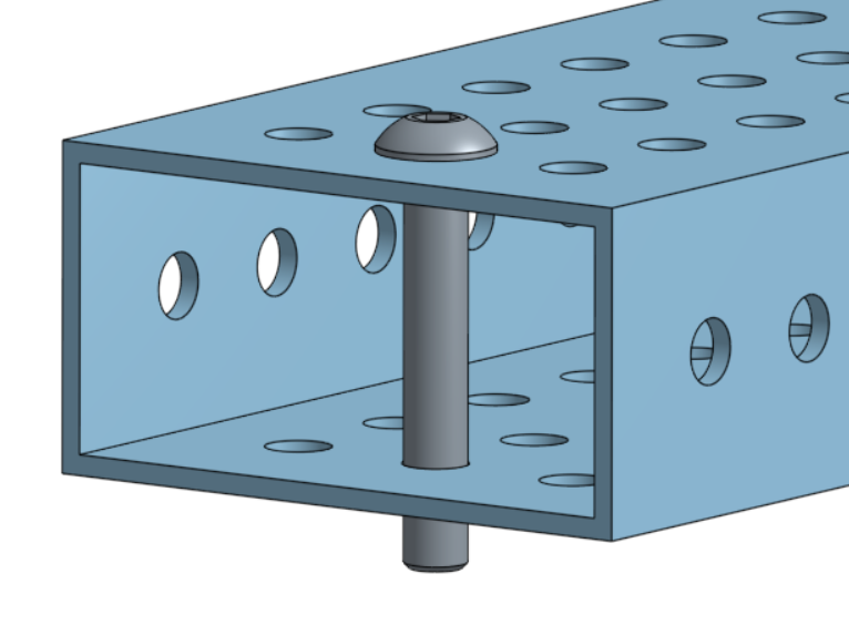
Crush Blocks
When adding bolts through box tubes, especially 1/16” tube, the force of the bolt can crush the tube. Crush blocks help to spread out the force from tightening the bolt and prevent the tube from crushing. MKCAD has a configurable tube plug generator to quickly make crush blocks with settings for a variety of tube types and thicknesses.
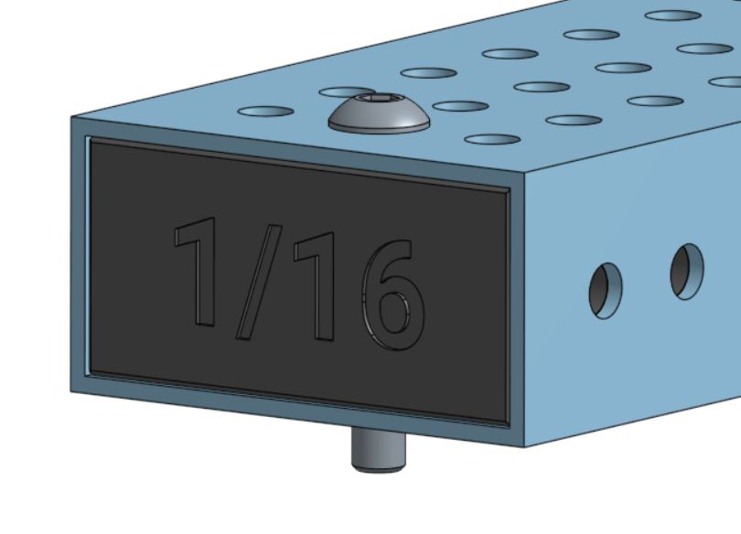
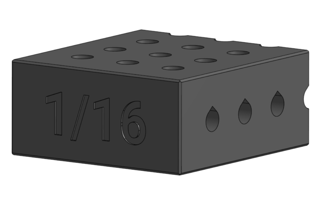
Tricks for Printing Crush Blocks
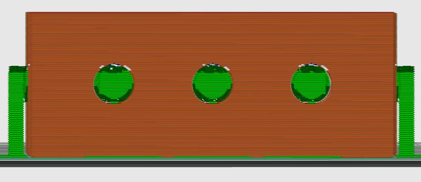
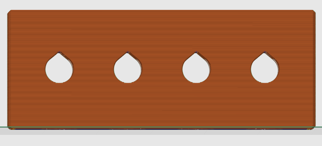
Due to the way 3D printers work through printing layer by layer, holes can end up becoming distorted when printed with their axis parallel to the build plate. This is because gravity will pull down on the hot filament as it's printed, creating a “squished” circle hole. One solution is printing with supports, but these supports can often be difficult to get out especially in longer holes. An easy solution to this problem is to use teardrop geometry to allow for printing without supports. This works by eliminating the "overhang" or areas on a 3D print that are not at least partially supported by the layer below them. To do this successfully you will need to plan for what face of the print will be touching the build plate when printed.
Power Transmission
Pulleys
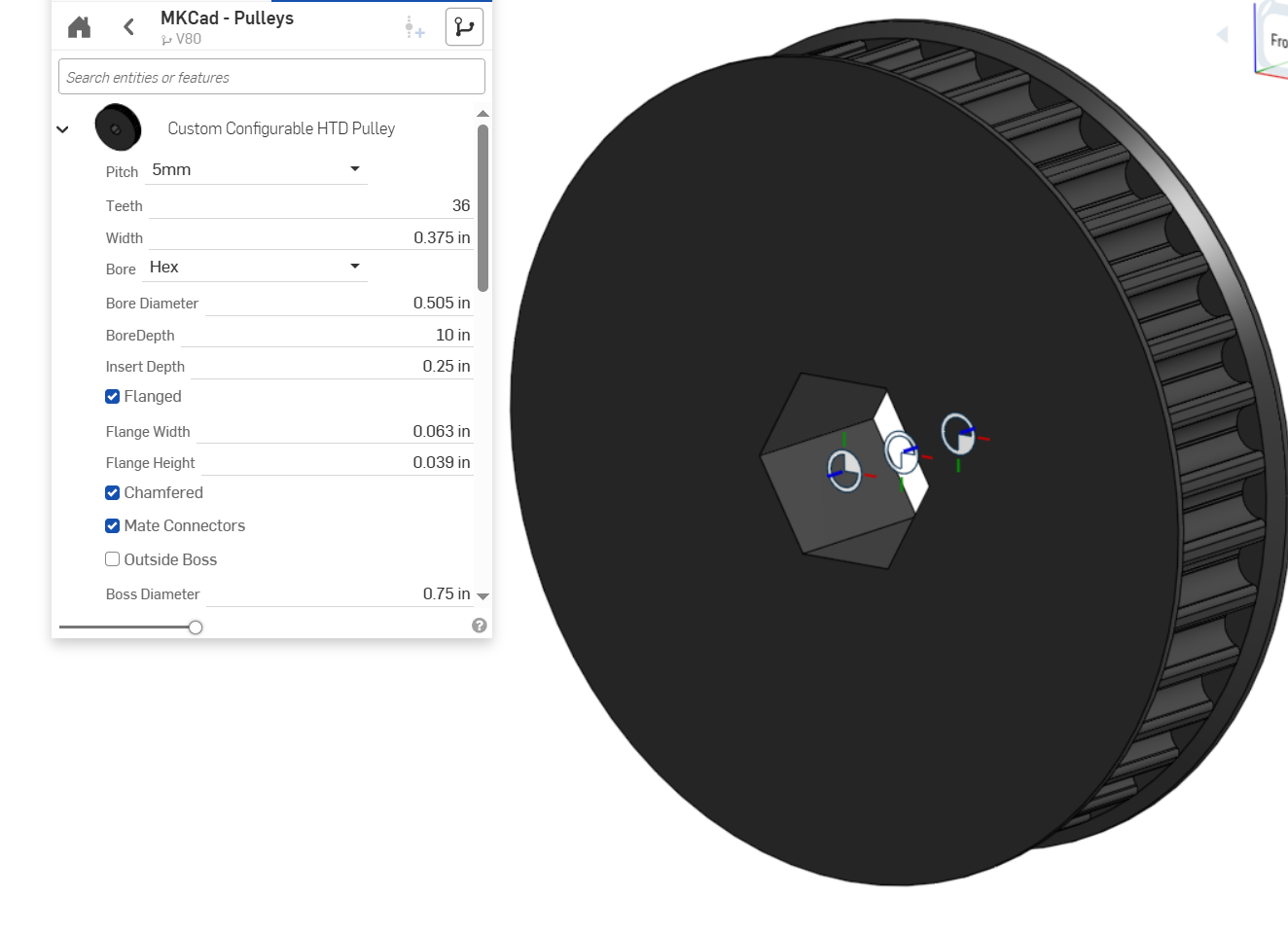
Pulleys can be a great option for 3D printing. 3D printing allows you to make any number of teeth and customize how the pulley will mount to other geometry.
Tips for Printing Pulleys
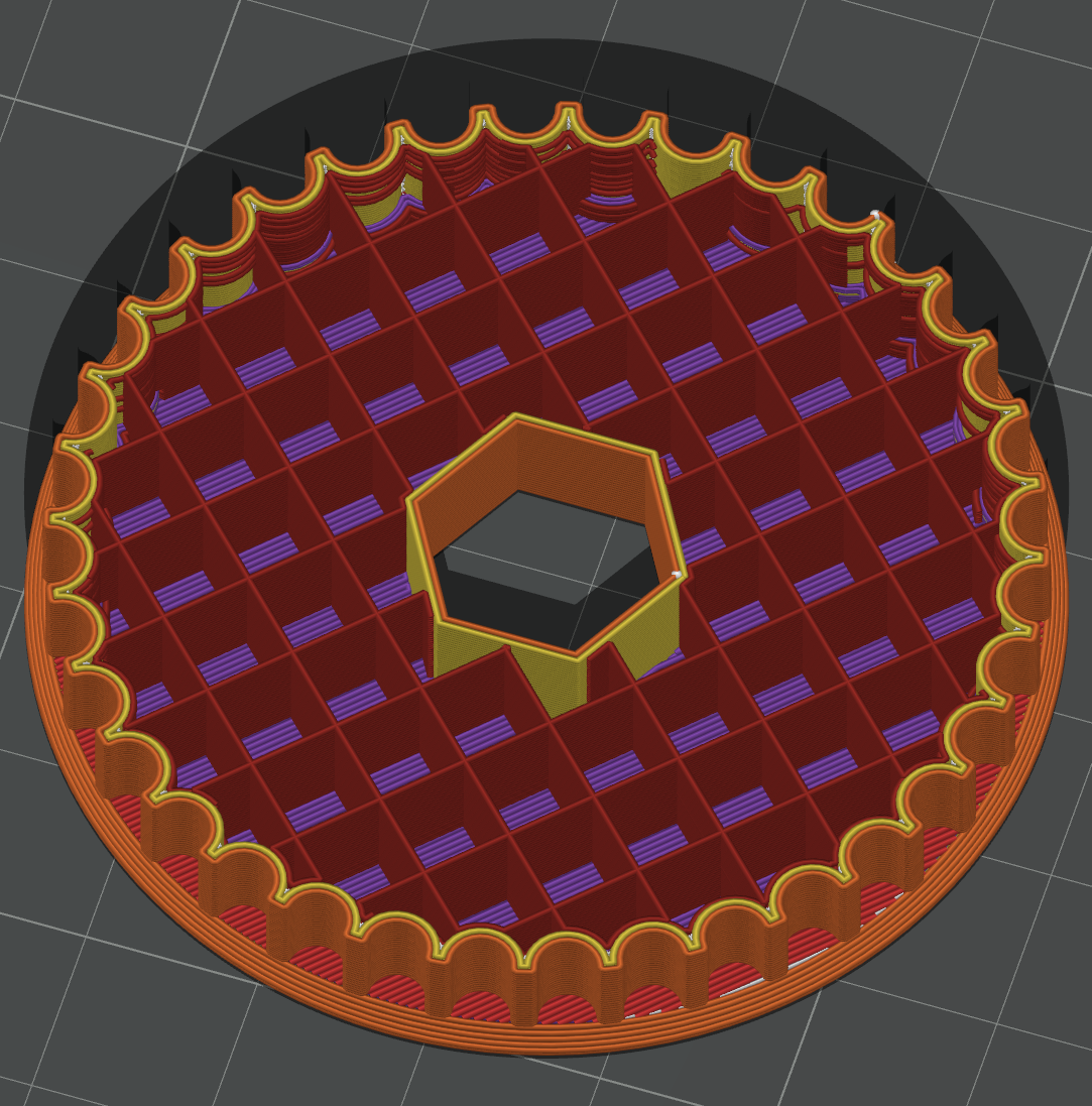
Infill: Power transmission parts may need to be printed with more walls and higher infill percentage (density of the inside of the part). Depending on the use case it might even be necessary to print at 100% infill. Using lower infill will decrease print time and decrease weight, but might increase risk of the part breaking.
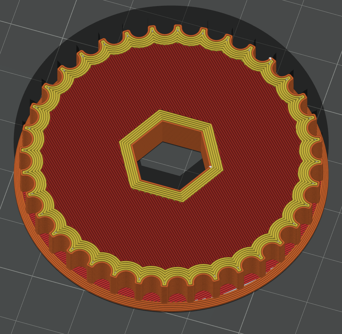
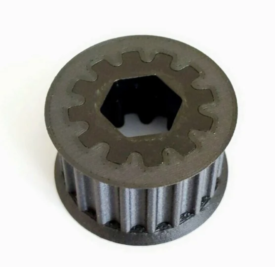
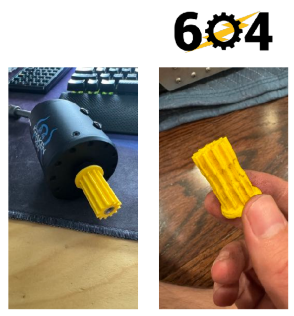
Hex Shaft Inserts: Compared to metal, plastic is relatively soft and can be worn down over time. High amounts of torque from a hex shaft (especially Thunderhex, which has rounded edges) can turn the hexagonal hole of a 3D printed pulley into a round hole, eventually eliminating power transmission between the shaft and pulley. One way to fix this is by using metal inserts that help to distribute the forces of the hex shaft into the printed part away from the hex bore.
Gears
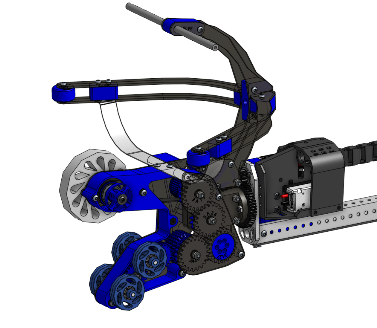
Gears can be 3D printed depending on their use case. In general applications with high torque requirements are not well suited for 3D printed gears. However things like claws or secondary mechanisms can benefit from the weight savings and flexibility of 3D printing. In the example below, 3005 Robochargers made great use of 3D printed gears in 2023 on their end effector.
Tips for Gears
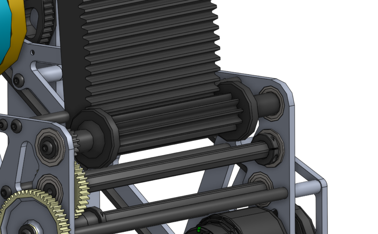
Face Width: Face width refers to how much surface area is in contact between two gears. This can also be thought of as how “thick” the gear is. Having a larger face width reduces the stress on the gear and makes it less likely to break.
Tooth Strength: Using a lower diametral pitch (fewer teeth per pitch circle length) will make the teeth thicker, in turn making the gear stronger. Both of the above principles were used by 2910 in this example of their 2022 shooter hood.
3D printed gears must be used with caution in high torque applications like motor pinions or drive gears, using 3D prints in these applications can lead to the gears becoming worn out quickly.
Sprockets
Many of the same principles from above also apply to sprockets. Care must be exercised to ensure the loading of the sprocket doesn’t exceed the strength of the printed material. Because there isn't any torque transmission, 3D printed sprockets can sometimes be useful as idler sprockets for chain tensioners, again depending on the load requirements and strength of filament.
Custom Brackets and Structure
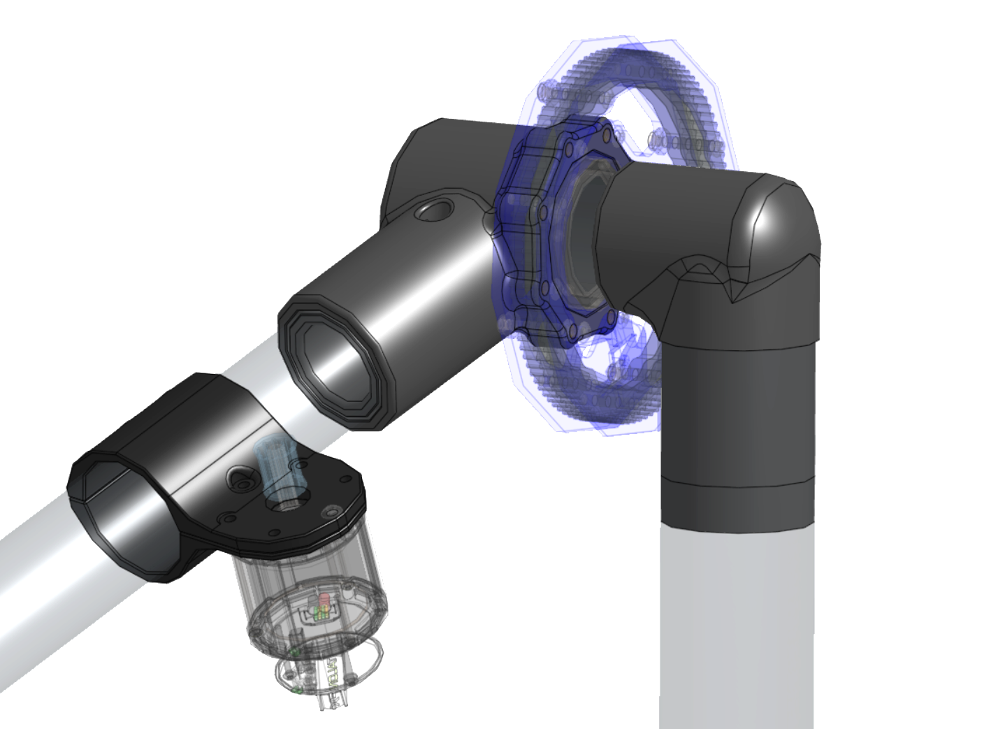
3D printing is an exceptionally good solution when oddly shaped geometry is required. For example, 5460's arm in 2023 was built with geometry that would be very challenging or expensive to make with conventional machining methods.
Caution needs to be exercised for most structural parts, however. Parts that are prone to shock loads will be at risk of breaking or shattering.
Tips for Custom Brackets
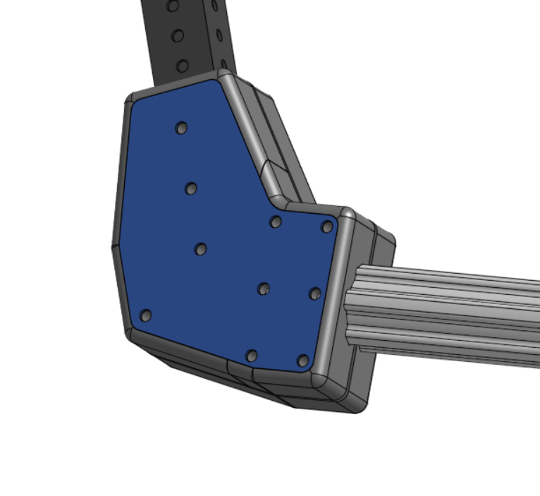
When designing custom brackets, it's critical to think about how the part will be assembled on the robot. Making parts easily serviceable will make your robot more reliable during competition.
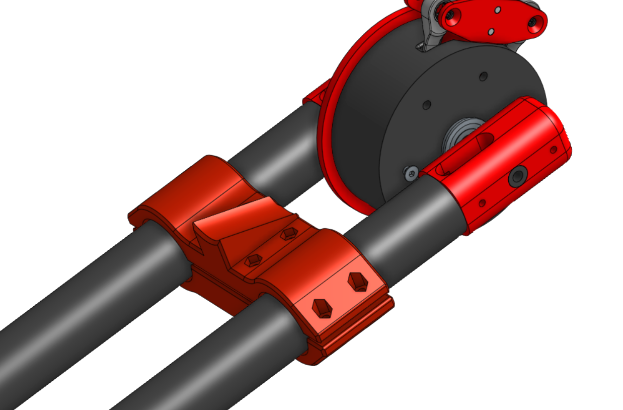
This example above is a perfect use case for 3D printing because it allows for a very precise arm resting angle to be set. This is beneficial for programming to ensure the arm starts in the same position every match. The split design of the part is very beneficial as it can more securely clamp the tubes, with the added benefit of being easier to replace. By splitting the part, each piece will have a flat surface that can be oriented down when printing reducing the amount of supports required.
Sometimes 3D prints might not be strong enough on their own to withstand high force applications. One option is to surround a print with metal plates for bolts to clamp on to. This distributes the load of the bolts and keeps the print compressed together, reducing the chance of it breaking.
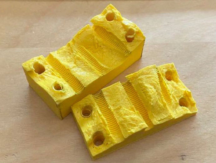
Unique Fastening Methods: Sometimes parts can retain fasteners to make the part easier to mount. This is especially useful if you want a surface free from bolts/nuts such as a game piece centering feature.
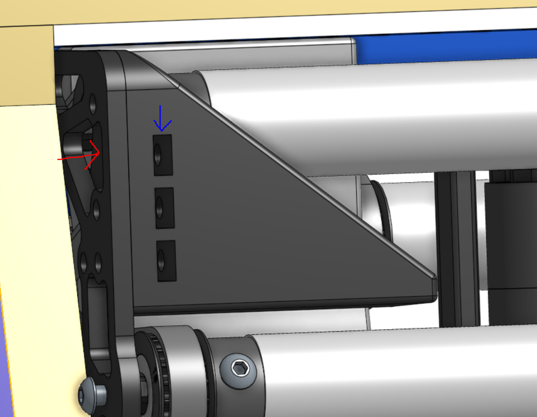
The above 3D print was designed for centering a game piece. It's mounted with square nuts placed into rectangular channels, and bolts are run from the outside to hold it to the mounting plate. This is advantageous because there are no bolts or nuts on the centering surface that the game piece could get caught on.
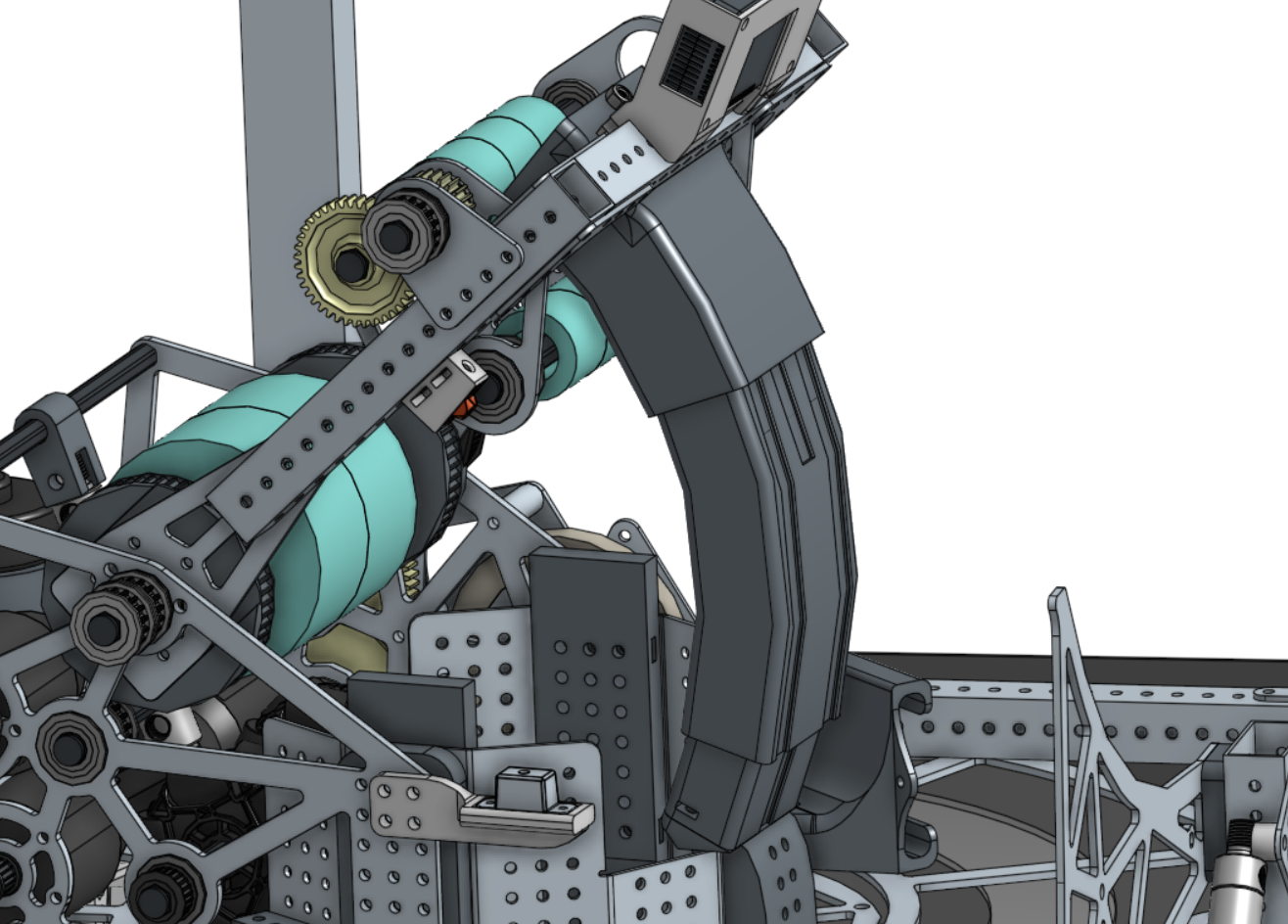
This arc feature from 1678 helps guide the game piece through their adjustable shooter. 3D printing is a perfect solution for this level of geometric complexity.
Part Orientation: Part orientation on the build plate greatly affects strength, support needs, and print time. Prints are typically strongest in the x-y plane of the printer as in the z direction the layers can delaminate (pull apart). The reduced strength in the z direction occurs at the layer interface because the previously deposited filament has cooled before the next layer is extruded. Since polymers at different temperatures do not fuse as effectively as those at their melting point, the resulting adhesion between layers is weaker.
This picture shows a solid part on the left vs an FDM printed part. The left part is “isotropic” meaning it has consistent material strength throughout, while the part on the right is "anisotropic" meaning it has different characteristics depending on the direction. The layer to layer bonding is the weakest area of the print and failed in this test.
Material Choice: Material choice can lead to a massive difference in the performance and reliability of your part. For example within the lineup of filaments from Bambu Lab (a 3D printer company), PETG offers significant improvement in impact strength and tensile strength over the more common 3D printing filament PLA. Polycarbonate has nearly double the tensile strength and bending strength of PLA (when properly annealed to filament specs) and it has nearly 50% higher impact strength (although it is much more difficult to print). Carbon fiber infused filaments offer similar performance improvements, and high end CF filaments can achieve specs closer to aluminum than PLA. Additionally For some applications that are prone to shock loads or impacts, TPU can be very viable. High stiffness TPU isn’t particularly strong in tension, but has nearly 6x the impact strength of PLA.
Sensor Mounts
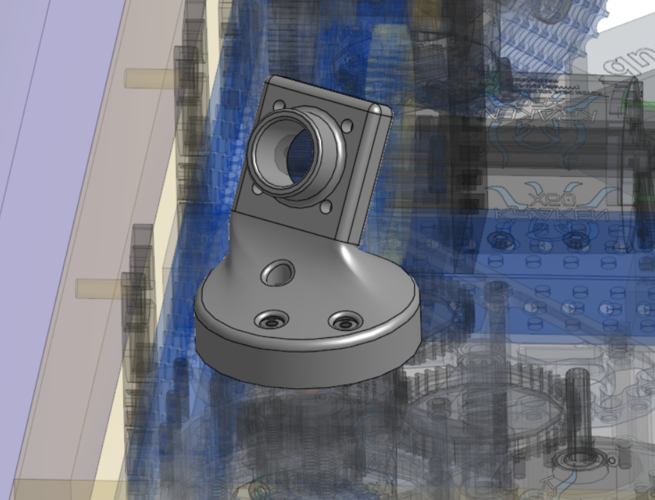
3D printing is a great solution for mounting sensors or cameras as these devices often need to be located very precisely at specific angles. 3D printing makes it very easy to iterate and optimize things like camera angles to see particular April Tags or game elements. In the example below of 6328’s camera mount they were able to create a part that would have been pretty complex to make with any other manufacturing method.
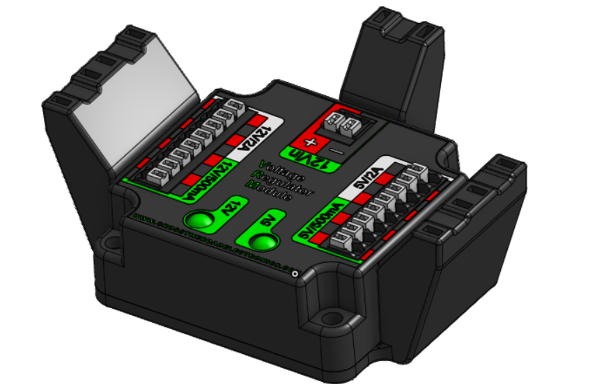
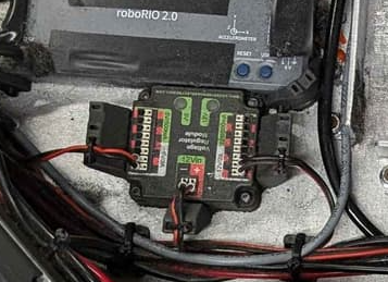
One of the other areas that 3D printing excels at is for adding strain relief to electronics. In the example below there are channels at the top of the part that a zip tie can be fed into to tie down wires entering the VRM. This helps prevent wires from being pulled out of their terminals. This same concept can be applied to any part where wires need to be secured.
Tips for Sensors and Strain Relief
For sensor mounts that may get hit by game pieces or other robots, consider more durable materials, specifically materials that have high impact strength. Impact strength is a measure of how well a material can resist breaking or shattering when subjected to a sudden force or shock such as a hit, drop, or collision. In FRC you may see significant usage of polycarbonate for both the construction of the field and high impact robot parts. This is due to polycarbonate's ability to withstand high impact force and return to its original shape. PC is possible to print on some 3D printers, but generally can be difficult to work with. TPU (Thermoplastic Polyurethane) is a rubber-like material that can be a great choice for a very high impact resistance material. An example of this is in usage is 6328 Mechanical Advantage printing their 2024 camera mounts out of TPU to make them more impact resistant. The slight flexibility of the material means the camera mounts are able to withstand impacts and spring back to their original position, ultimately preventing catastrophic part failures that could occur with weaker materials.
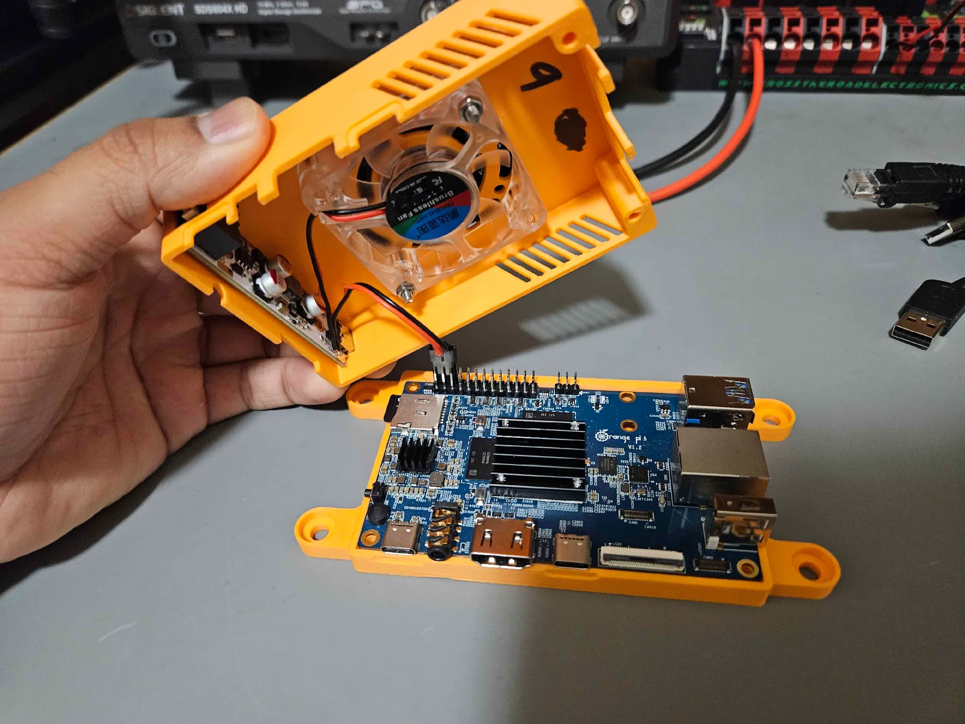
Enclosures for Electronics
Electronic enclosures are a great use case for 3D printing as they often rely on complex part designs and customizations for things like fans, power boards, mounting holes etc.
Tips for Electronics Enclosures
Ensure there are sufficient openings for wire routing, ventilation, and access to ports or LEDs. Secure components with secure mounting features, and plan for easy removal or maintenance during pit repairs.
Threading Into Parts: It may be desirable to have an enclosure or other parts that can be bolted together with threads in the part. However, after a few cycles of threading and removing a bolt the soft plastic threads will likely wear out. One alternative is to use a heat stake insert. These inserts are placed in a hole in the print and melted into the plastic using a soldering iron or specialized heater. Once the plastic cools it retains the insert and prevents it from rotating when tightening a bolt.
Tools and Jigs
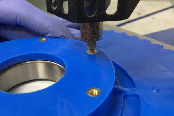
3D printing can also be used to make precise jigs and fixtures for common operations. In this example below the jig is used to make holes for a tube plug that need to be exactly 0.5” from the end of a tube.
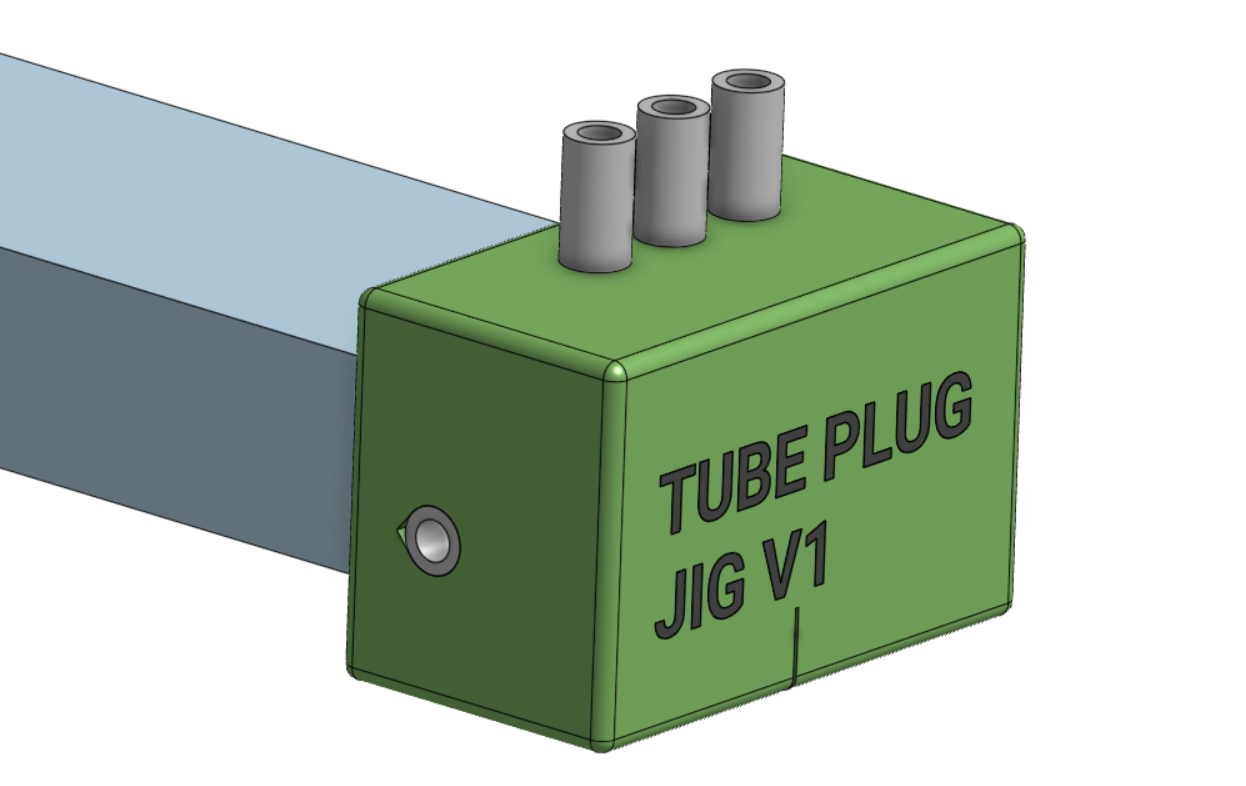
Tips for Tools and Jigs
In the part above metal drill guides are used to prolong the life of the jig. If the jig was only plastic then it would quickly get damaged from repeatedly drilling into the holes.
Other jigs that can be useful are jigs for drilling in the center of a tube, aligning a tap so it's perfectly straight, or marking a precise distance for cutting tubes and shafts.
Final Notes
Holes and Tolerances: Holes designed to exact CAD dimensions often print smaller due to material expansion/cooling. You can make test prints with varying hole tolerances to find optimal tolerances for your specific printer and material. (ex. for a nominal hole size of .2” you could print a test part with holes of .18”, .19”, .20”, .21” , .22” etc). Finding the closest hole size to your target will tell you what you should use in CAD for the hole size.
Optimize for Overhangs and Supports: An overhang is anywhere on a part that isn't supported from below. Some printers can handle angles as low as 30 degrees from the print bed plane without support material (extra material used to hold up the part during printing). Reducing overhangs will reduce filament wasted on support, improve the surface quality and accuracy of the part, and can reduce print time.
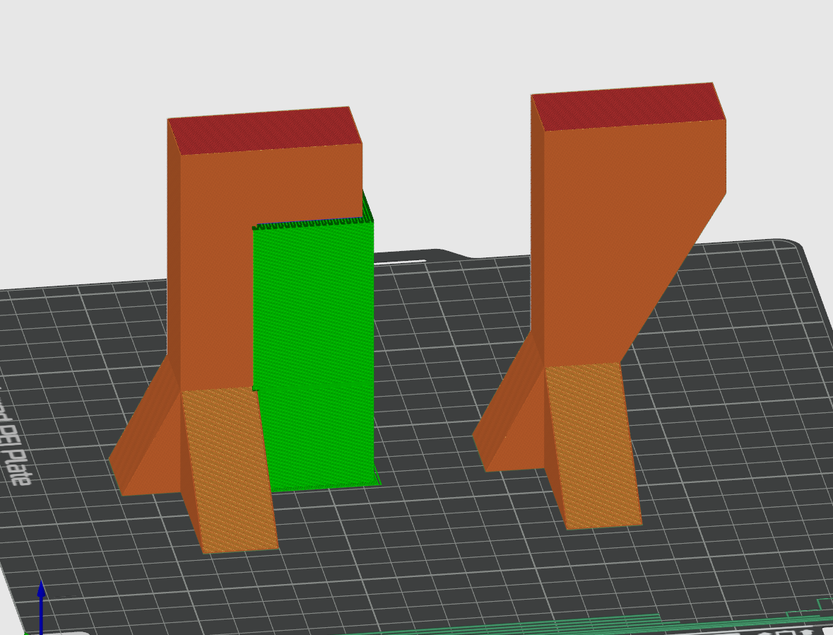
The part on the left with an overhang held up by support material (green) uses 23% more filament to print than the part with extra geometry added on the right. Additionally the part on the right will be stronger because the overhanging feature is better supported.
Fillets vs Chamfers Fillets are a great way to make your parts smooth and, in some instances, more precise. A typical FDM 3D printer involves a toolhead moving at high speed, and rapid changes in direction (for example a 90 degree corner) will not be perfectly sharp leading to slight deviations in the size of the corners. This can be problematic for parts that need to fit together, but can be easily solved by adding a fillet to smooth out the sharp edge. However, fillets on the part surface touching the print bed can lead to part warping due to the same overhang issue discussed above. Replacing the fillet with a chamfer at an angle your printer can print without supports can fix this problem.