Part Studio Best Practices
What to Include in the Part Studio
The part studio should contain all parts that need to be manufactured by your team. This could include fully custom plates, shafts cut to length, modified COTS parts, etc. Unmodified COTs parts should be imported directly into the corresponding assembly - no modification inside the part studio is required.
Also avoid duplicating identical parts and over-using intensive featurescripts, such as tube converter. These practices can make your part studio loading times high and navigation and changes very laggy. Creating only one of each part in the part studio means you can simply duplicate it when assembling while your part studio performance will be greatly improved.
Tip
Instead of deriving COTS parts for reference, usually you can add simple measurements in your sketches (like a pitch circle instead of a derived gear); this is faster both in the moment and overall as it decreases load times. You can derive parts from your other subsystems (such as the frame and simplified modules from your drivetrain part studio into your intake part studio) and make them closed composites for easy reference, but keep it to a minimum.
Feature Tree Organization
Every part studio feature tree should start with a derive command, pulling from the relevant main layout sketches. This is what you will build on.
Sort and name the features, parts, and tabs and use folders to make your CAD more understandable for other people working on the robot. One of the biggest benefits of Onshape is its collaborative capability, but unnamed and unsorted documents eliminate that point entirely. Sorting and naming in real time can also make it easier to go back and change things (which you will inevitably need to do). Some teams even use a part naming system to assist with organizing manufacturing and assembly.
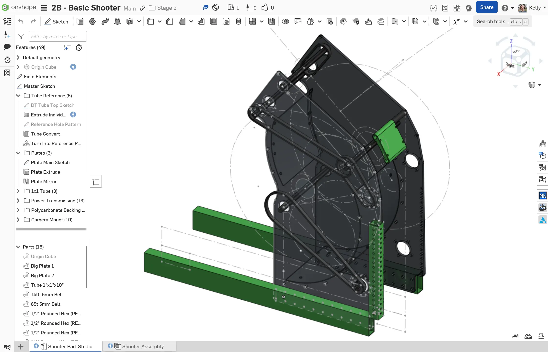
See an example of a well-organized part studio here:
The Importance of Intelligent Origins
As with many other good practices in CAD, smart origins can make future you's life easier. Intelligent origins allow designers to leverage default geometry (Front/Right/Top Planes, Origin Point) for robust axes of symmetry and references in their models.
For FRC CAD, the purpose of using the same origin as the main layout sketch across all studios and assemblies is twofold:
- The origin will always be a consistent central point you can reference. This helps keep things parametric too.
- To unify the robot CAD and robot software origin point. By having the same origin in CAD and code, the robot can be seamlessly exported to AdvantageScope and camera transformations more easily measured.
Note
Although definitions may vary from team to team, the origin of an FRC robot is typically defined as the center of the drivebase, on floor level.
One way to help achieve this is to use the Origin Cube Featurescript, which is further explained in the assembly best practices page. If using the origin cube, make the origin cube the first feature in all part studios.