Assembly Best Practices
Assuming you have already named your parts and organized your work within the rest of the document, creating a well-organized assembly is very straightforward.
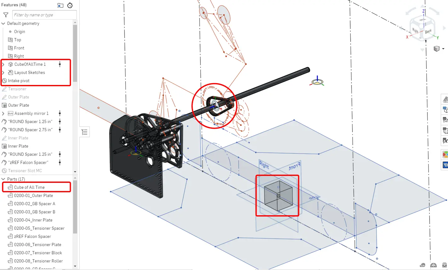
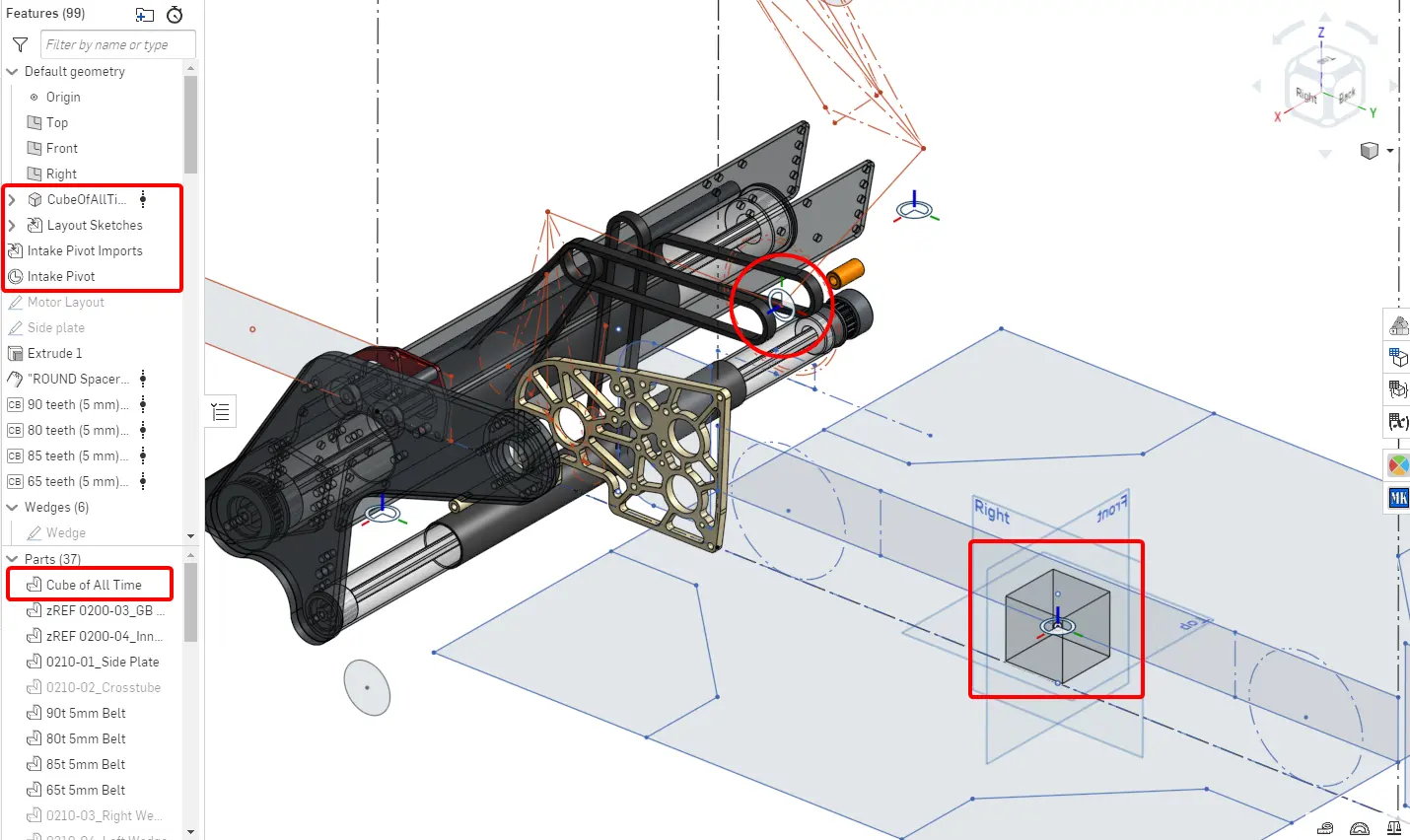
The Origin Cube
The Origin Cube Featurescript inserts a 2" transparent cube at the origin of the part studio. The cube has a mate connector at the origin. Because this part will never change and always stays at the origin of the part studio, using it to group and fasten parts to the origin will always be more robust and parametric than fixing or using a mate connector attached to another part, as that part may change or be deleted.

Tip
The origin cube has the option of importing a number of useful constants and functions, including bolt hole sizes, gear outer diameter, and a center-to-center calculator.
Process for Inserting Parts
As is described in Sub-Document Setup, subsystems with no degrees of freedom will only have one assembly, while subsystems with multiple moving parts are separated into multiple rigid assemblies. The process for inserting parts and finishing assemblies is similar for both circumstances.
- Create the origin cube in your part studio
- Insert the related parts and origin cube into a new assembly document for a rigid subassembly
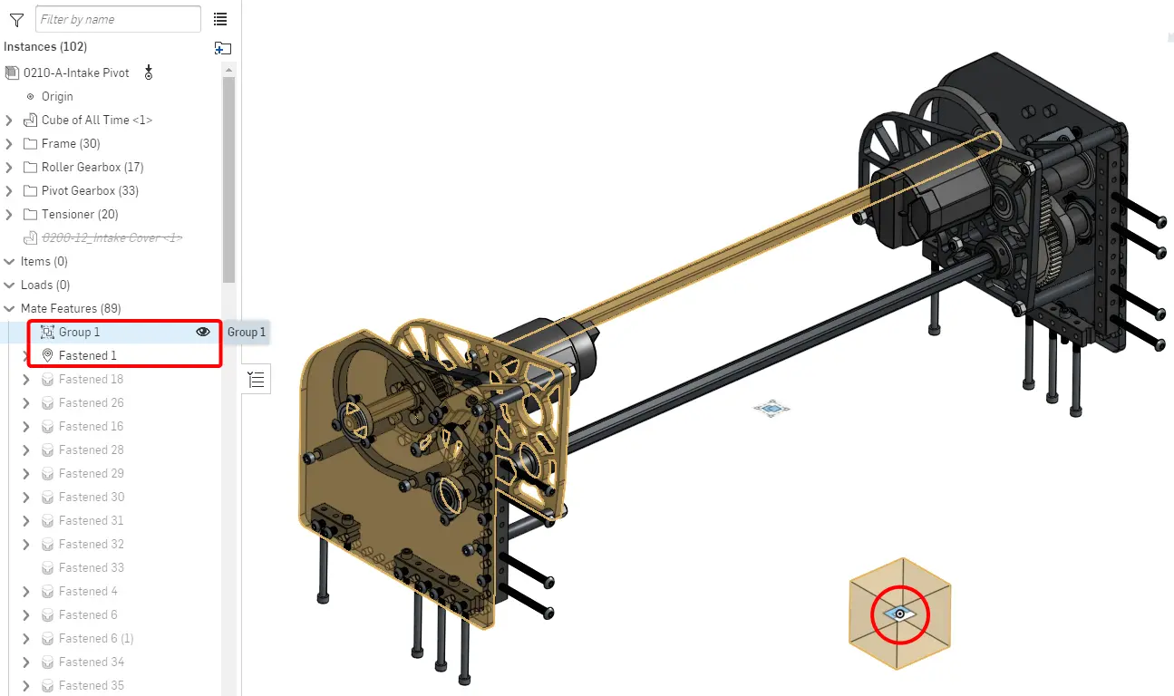
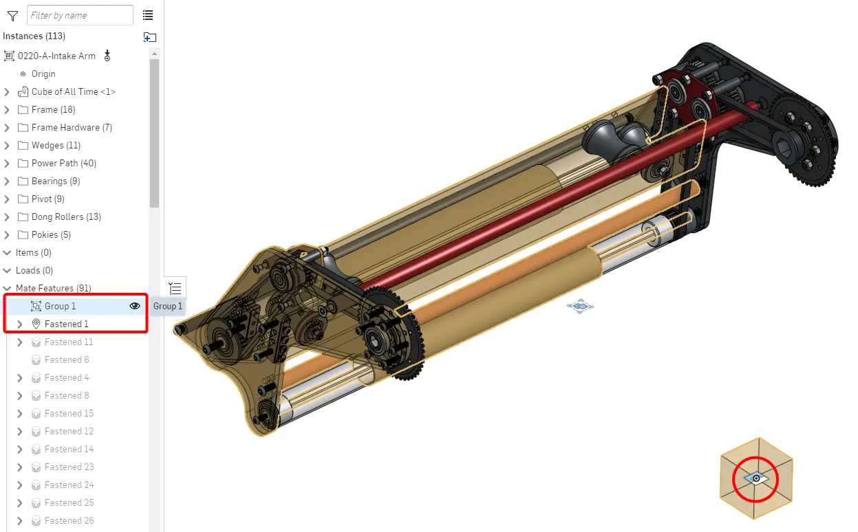
- Use the "group" tool on all parts
- Fasten the origin mate connector to the origin
- Duplicate and fasten any duplicate parts
- Insert standard hardware and COTS components
- Sort the instances into folders (i.e. tubes, swerve modules, spacers)
Tip
As you add more parts in the part studio, you can insert them individually into the assembly with the green checkmark, double click on the initial group, and add the part to the group to avoid mating it. This means that new part will always stay in the same place relative to where it was designed in the part studio.
If the subsystem has multiple moving parts (like an over-the-bumper intake or elevator), create a mate connector on the main layout sketch for each degree of freedom. This may be a pivot point or the starting point of a slider mate (in the case of an elevator). Make each mate connector owned by the origin cube.
Repeat steps 2-7 of the process for all other rigid subassemblies, if applicable. This will result in each subassembly being rigid, with the origin cube fastened to the origin and all the parts in the same place as in the part studio. Each subassembly will also contain the mate connectors owned by the origin cube.
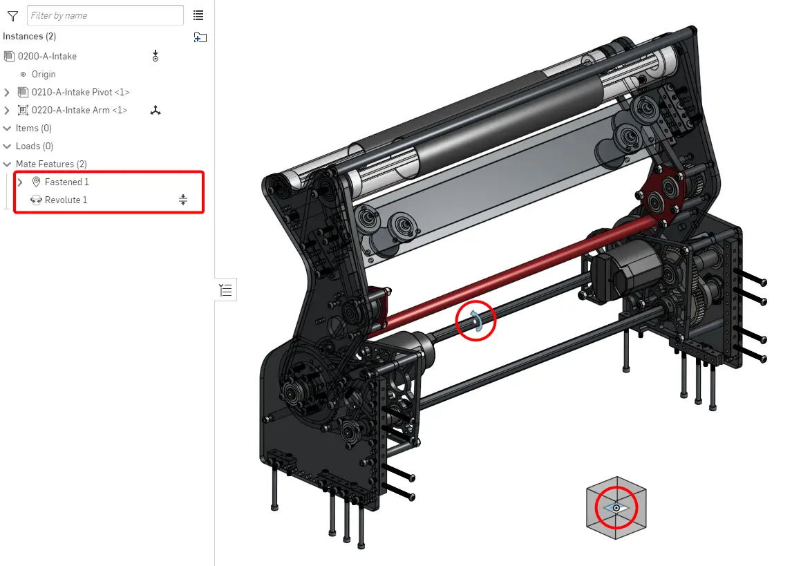
Now create a top-level subsystem assembly and insert each subassembly into it. Fasten the origin cube of the static subassembly to the origin, and use the other mate connectors to mate the other subassemblies together.
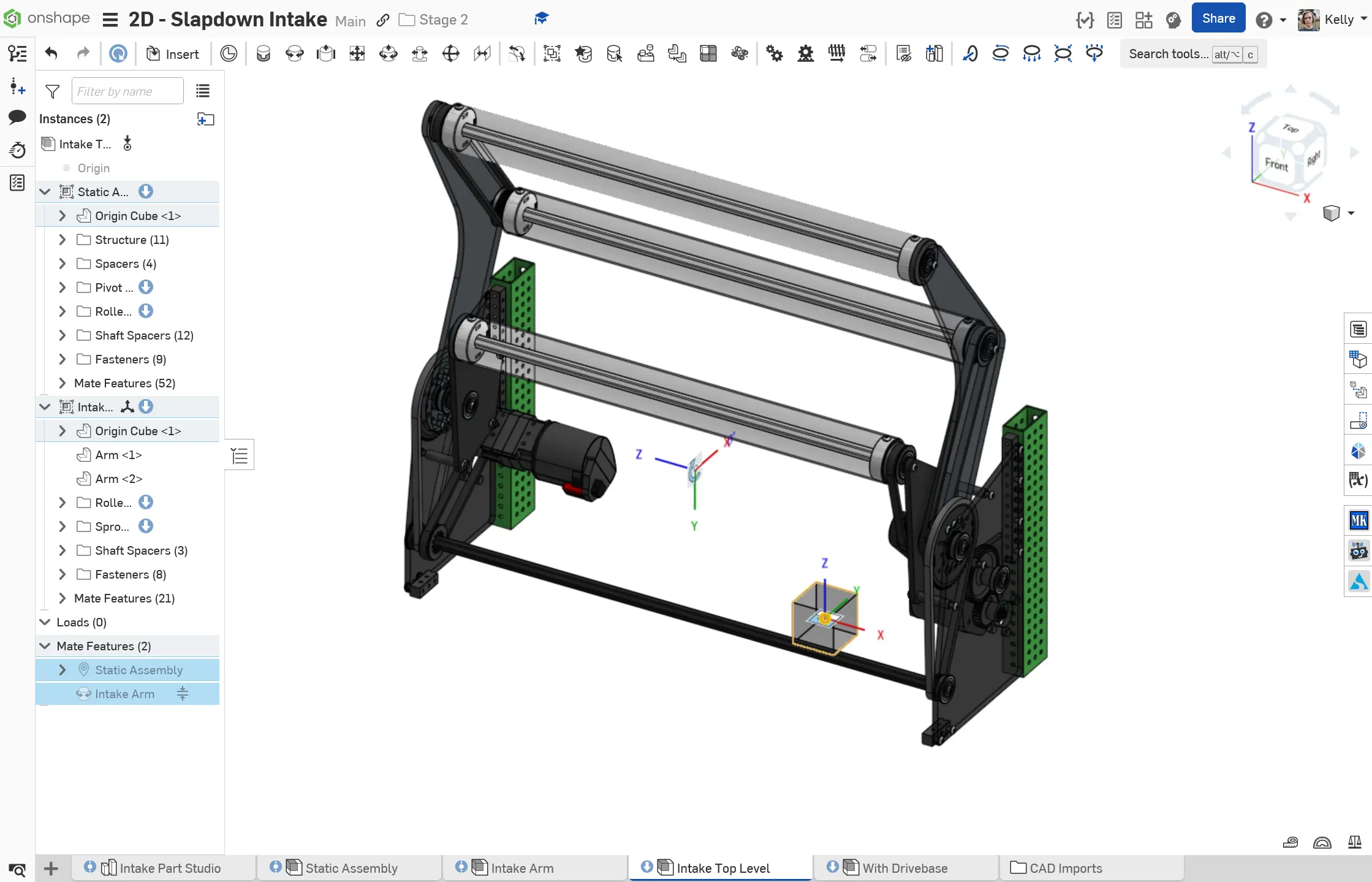
Stage 2C - Slapdown Intake
The Stage 2C Slapdown Intake is a subsystem with a static portion and a pivoting portion. An extra mate connector is added for the pivot on the main layout sketch, owned by the origin cube
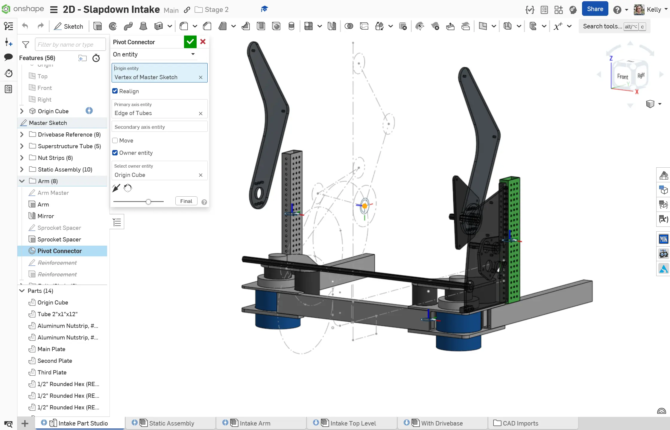
This mate connector exists in both subassemblies.
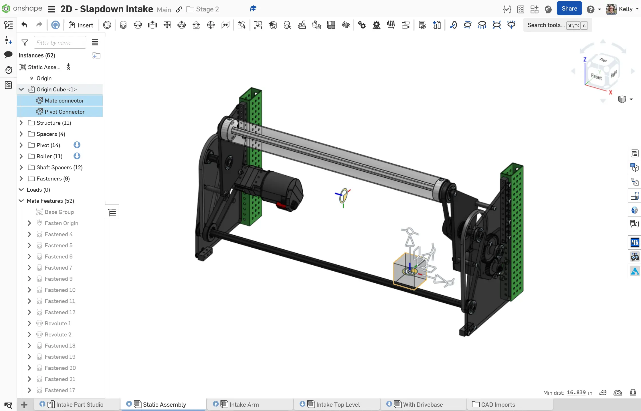
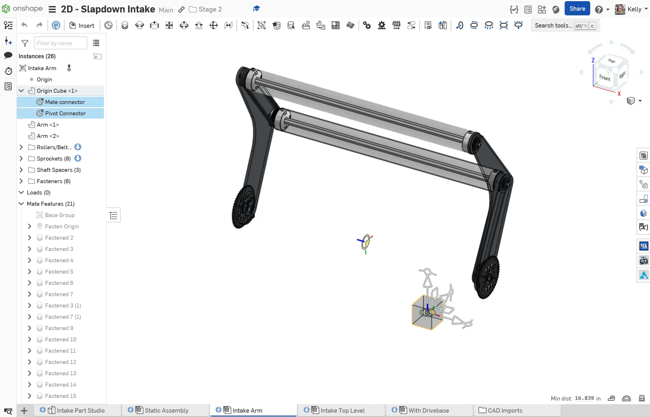
The static assembly is fastened to the origin and the arm assembly revolves using the pivot mate connector owned by both instances of the origin cube.
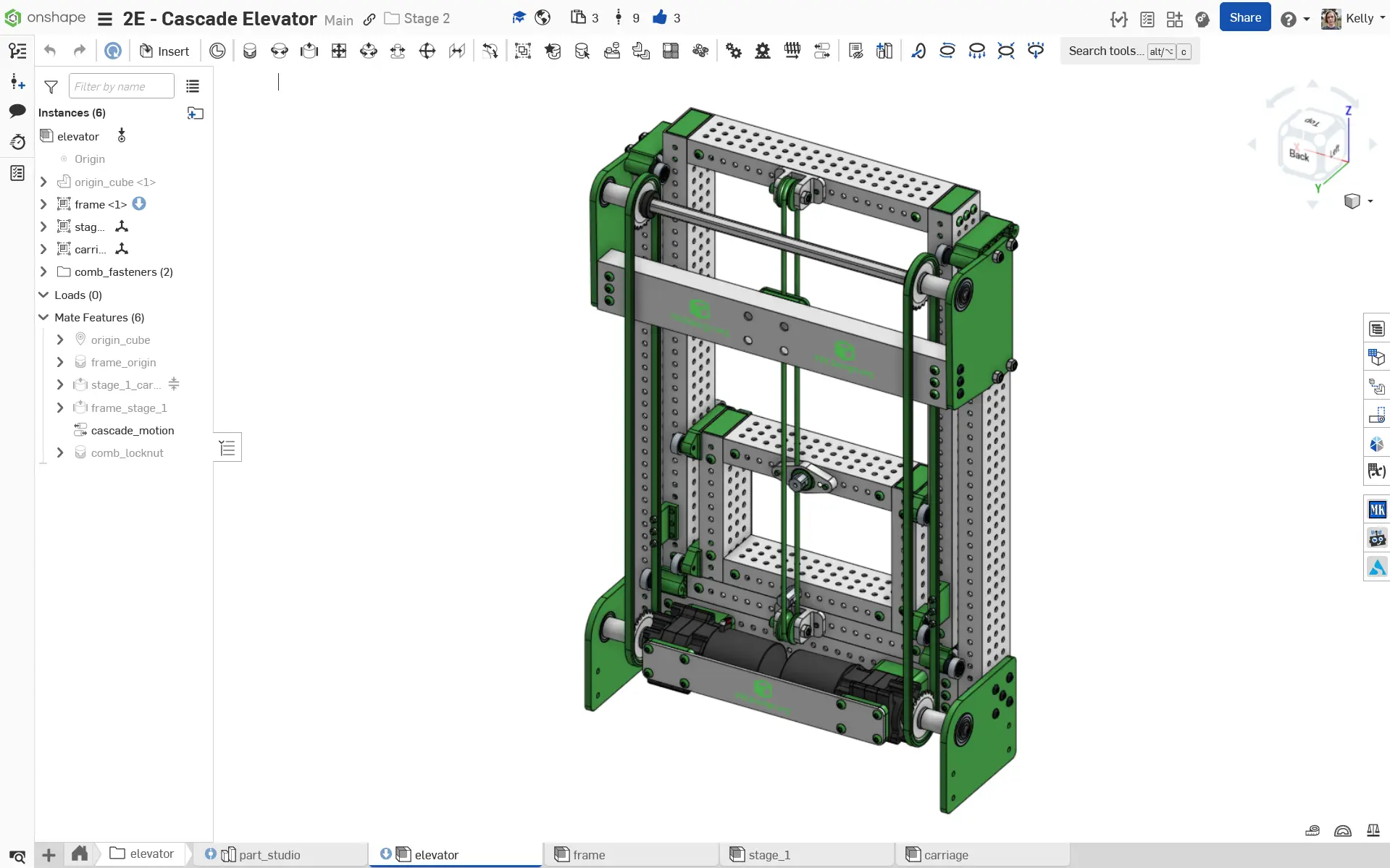
Stage 2D - Cascade Elevator
The Stage 2D Cascade Elevator is a subsystem with a static portion and two subassemblies that slide linearly. This contains a part studio, a static frame/gearbox assembly, assemblies for the first stage and carriage, and a top-level assembly combining the 3 subassemblies with slider mates.
3647 Millennium Falcons 2024 Intake
Simplified Models
Make sure to minimize primitives in your assembly. Primitives are a measure of how complex an object is and how hard it is for Onshape to render. The more primitives there are, the more laggy your assembly will be.
Use simplified modules from FRCDesignLib wherever possible to minimize primitives: electronics, swerve modules, motors, etc.
Minimize Primitives
Other Small Things
- Import COTS parts from FRCDesignLib
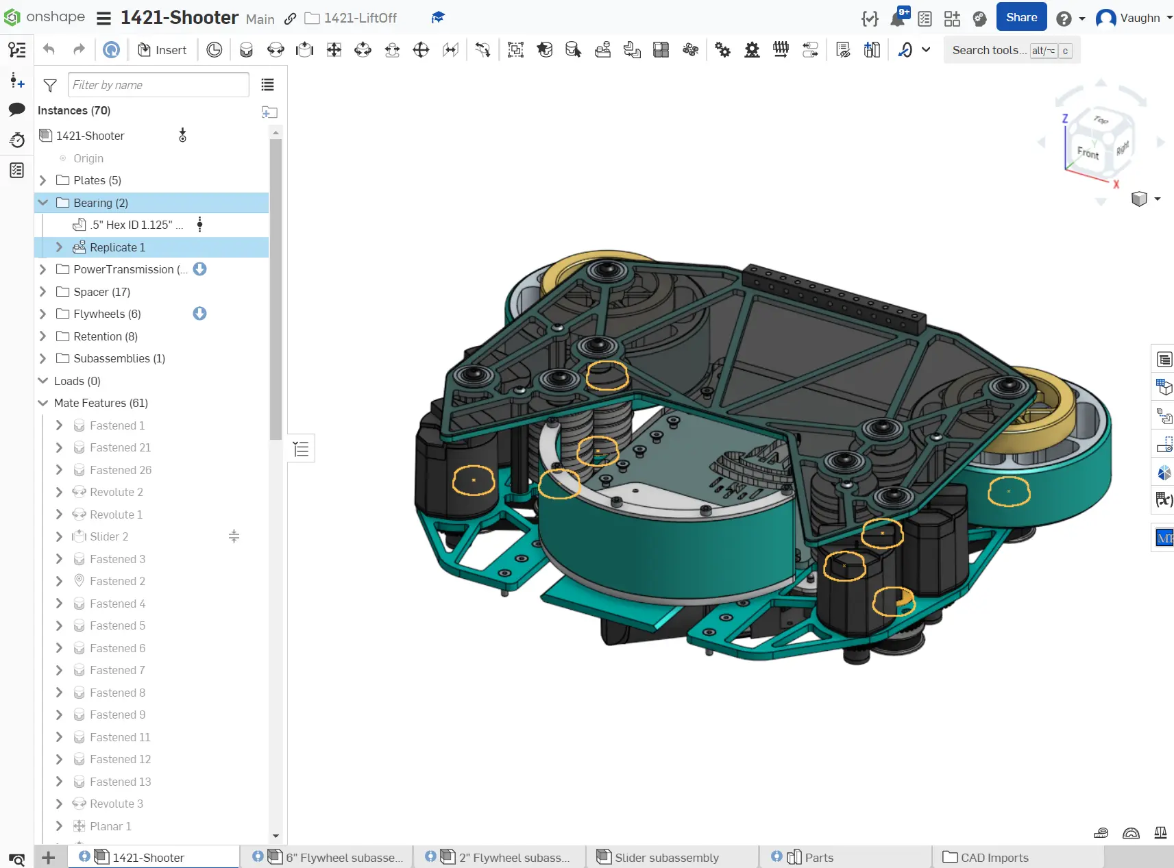
- Use the replicate tool for adding hardware!
- Minimize the number of mates you use; this lowers the solve time
- Stay organized with folders
See a well-organized assembly here: